

Screw thread detecting method and device
A detection method and thread technology, applied in image data processing, instrumentation, calculation, etc., can solve the problem of low accuracy of screw thread detection
- Summary
- Abstract
- Description
- Claims
- Application Information
AI Technical Summary
Problems solved by technology
Method used
Image


Examples
Embodiment 1
[0033] Before introducing the embodiments of the present invention, the application scenarios of the screw thread detection method in the embodiments of the present invention will be described first. The detection of screw threads is mainly carried out by a turntable or crawler-type screw detection machine. The screw thread detection machine is equipped with a corresponding industrial camera at a fixed position for image acquisition of screws, and then through the screw thread detection machine. The images are sent to the processing center for inspection. Wherein, the processing center includes but not limited to the PC terminal, the data processing center unit of the screw thread detection machine, and the cloud processing server.
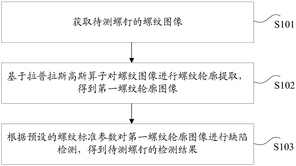
[0034] According to an embodiment of the present invention, a screw thread detection method is provided, such as figure 1 As shown, the method includes:
[0035] S101, acquiring a thread image of the screw to be tested;
[0036] S102, extractin...
Embodiment 2
[0067] According to an embodiment of the present invention, a screw thread detection device for implementing the above screw thread detection method is also provided, such as image 3 As shown, the device includes:
[0068] 1) an acquisition unit 301, configured to acquire a thread image of the screw to be tested;
[0069] 2) The extraction unit 302 is used to extract the thread profile from the thread image based on the Laplacian-Gaussian operator to obtain a first thread profile image;
[0070] 3) The detection unit 303 is configured to perform defect detection on the first thread profile image according to preset thread standard parameters, and obtain a detection result of the screw to be tested.
[0071] As a preferred technical solution, in the embodiment of the present invention, the device further includes:
[0072] 1) The first determination unit is used to determine the screw to be measured in the thread image based on a preset boundary algorithm before extracting t...
Embodiment 3
[0080] According to an embodiment of the present invention, there is also provided a storage medium, which is characterized in that the storage medium includes a stored program, wherein, when the program is running, the screw thread detection method as described above is executed.
[0081] Optionally, in this embodiment, the storage medium is configured to store the following program codes:
[0082] S1, acquiring the thread image of the screw to be tested;
[0083] S2, extracting a thread profile from the thread image based on a Laplacian-Gaussian operator to obtain a first thread profile image;
[0084] S3. Perform defect detection on the first thread profile image according to preset thread standard parameters to obtain a detection result of the screw to be tested.
[0085] Optionally, for a specific example in this embodiment, reference may be made to the example described in Embodiment 1 above, and details will not be repeated here in this embodiment.
[0086] Optionally...
PUM
 Abstract
Description
Claims
Application Information