A battery liquid injection vibrating device

A vibrating device and liquid injection technology, which is applied in the direction of battery pack components, circuits, electrical components, etc., can solve the problems of low liquid injection efficiency and long battery cell injection time, shorten the liquid injection time, and prevent fixed Steady or leaky, easy to operate

Pending Publication Date: 2018-12-28
JIANGSU KATOP AUTOMATION CO LTD
View PDF0 Cites 0 Cited by
  • Summary
  • Abstract
  • Description
  • Claims
  • Application Information

AI Technical Summary

Problems solved by technology

[0003] Aiming at the shortcomings in the above-mentioned existing production technology, the applicant provides a battery liquid injection vibrating device with a reasonable structure, thereby solving the problems of too long liquid injection time of the battery cell and low liquid injection efficiency, and at the same time increasing the stability of the vibration device , to avoid the occurrence of leakage, etc.

Method used


Image

  • A battery liquid injection vibrating device
  • A battery liquid injection vibrating device
  • A battery liquid injection vibrating device

Examples


Embodiment Construction

[0023] The specific implementation manner of the present invention will be described below in conjunction with the accompanying drawings.

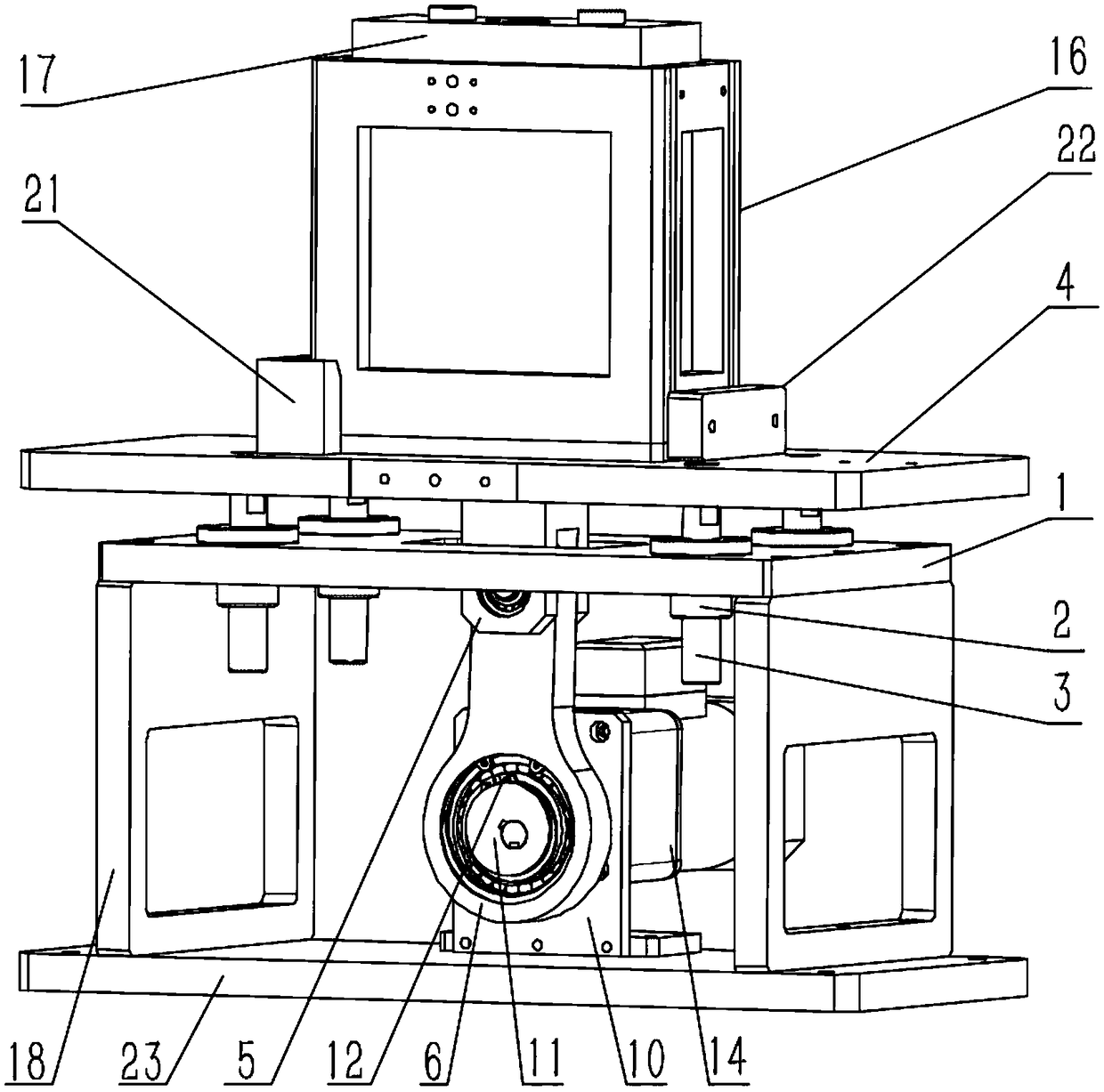
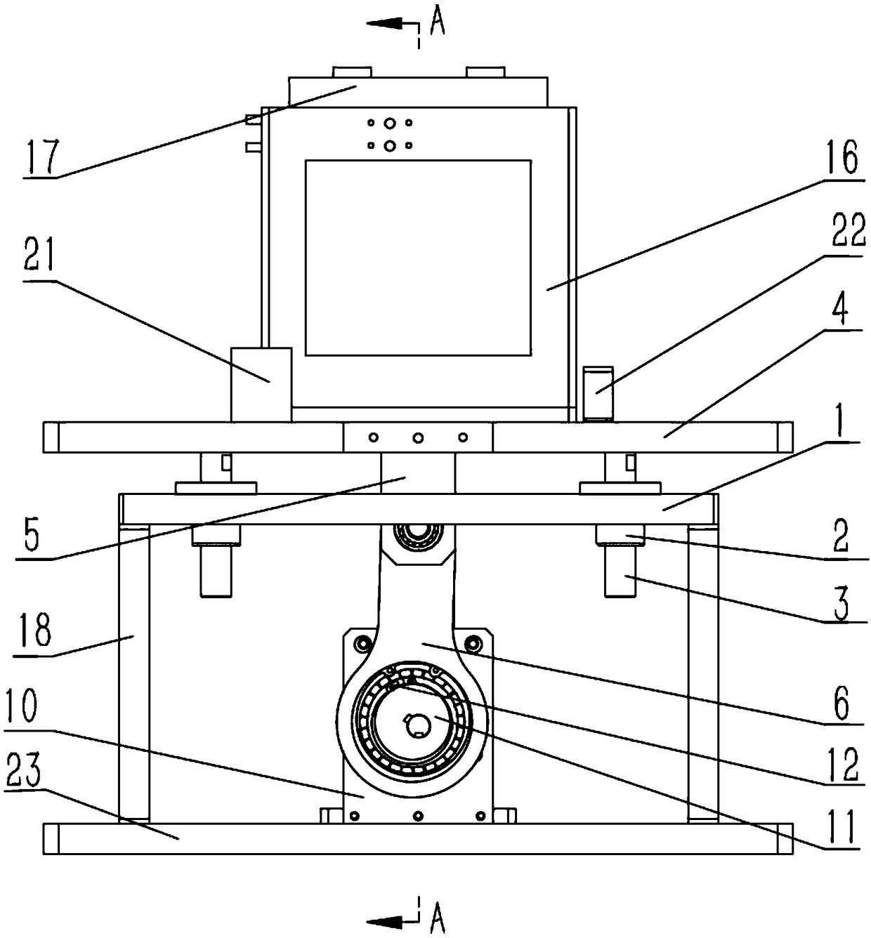
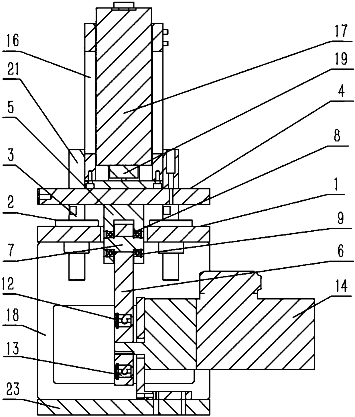
[0024] Such as figure 1 and figure 2 As shown, the battery liquid injection vibration device of this embodiment includes a horizontally installed bottom plate 23, two vertical plates 18 are installed at intervals above the bottom plate 23, and a fixed plate 1 parallel to the bottom plate 23 is installed on the top of the vertical plate 18 to fix A plurality of through holes are opened on the plate 1, and a guide post 3 is installed in the through hole through a linear bearing device 2, the guide post 3 passes through the upper and lower ends of the entire fixed plate 1, and a floating plate 4 is supported on the top of the guide post 3, floating A jig 16 is installed on the upper surface of the plate 4, and a cell 17 injected with heated electrolyte is fixed inside the jig 16 (heating temperature < 60°C); A motor 14 is fixed, an eccentr...


PUM


Abstract

A battery liquid injection vibrating device includes a horizontally mounted bottom plate, two vertical plates are arranged above the bottom plate, and a fixing plate parallel to the bottom plate is arranged on the top of the vertical plate, a plurality of through holes are arranged on the fixing plate, guide columns are arranged in the through holes through linear bearing devices, the guide columns pass through the upper and lower ends of the whole fixing plate, a floating plate is supported on the top of the guide columns, a fixture is arranged on the upper surface of the floating plate, andan electric core injected with hot electrolyte is fixed in the fixture; a motor is fixed on the bottom plate between the two vertical plates through a motor mounting plate, an eccentric wheel is mounted on the output shaft of the motor, the outside of the eccentric wheel sleeves a swing rod, the other end of the swing rod is movably connected with a connecting rod, a through hole is arranged in the middle of the fixing plate, and the top surface of the connecting rod head passes through the through hole and is locked with the bottom surface of the floating plate. The invention solves the problems of too long injection time and low injection efficiency of the electric cell, increases the stability of the vibration device and avoids liquid leakage and the like.

Description

technical field [0001] The invention relates to the technical field of battery liquid injection devices, in particular to a battery liquid injection vibration device suitable for square aluminum case (steel case) EV batteries. Background technique [0002] In the battery injection production process, the battery cell is usually injected with a liquid injection device composed of a cup body and a cup cover. Since the battery cell absorbs the electrolyte for a long time and the efficiency of one-time injection is low, it is necessary to The battery cell is heated and vibrated to increase its absorption rate of the electrolyte; most of the cell vibration devices used in the prior art are simple in structure and easy to operate, but due to their unreasonable structure, it is easy to cause the cell to be fixed unstable. lead to leakage, etc. Contents of the invention [0003] Aiming at the shortcomings in the above-mentioned existing production technology, the applicant provid...

Claims


Application Information

Patent Timeline
IPC IPC(8): H01M2/36H01M50/60
CPCH01M50/60Y02E60/10
Inventor 朱金鹏
Owner JIANGSU KATOP AUTOMATION CO LTD
Why Eureka
Try Eureka