Check patentability & draft patents in minutes with Patsnap Eureka AI!

An inertial rotary actuator having a composite foot mount

A technology of rotary drive and foot support, which is applied in the direction of piezoelectric effect/electrostrictive or magnetostrictive motors, generators/motors, electrical components, etc., and can solve problems such as complex structures and drive signals

Active Publication Date: 2018-12-28
JILIN UNIV
View PDF6 Cites 0 Cited by
  • Summary
  • Abstract
  • Description
  • Claims
  • Application Information

AI Technical Summary

Problems solved by technology

[0003]In order to solve the problem of complicated structure and driving signal of the current piezoelectric actuator, an inertial rotary actuator with a compound foot support is proposed, which consists of a fixed circumference, a center Composed of a rotating shaft, a piezoelectric vibrator, a connecting circle and a composite foot support; the fixed circle is connected to the frame, one end of the piezoelectric vibrator is connected to the central rotating shaft, and the other end is connected to the connecting circle, and the composite foot support Evenly arranged on the outer ring surface of the connecting circle, the composite foot support is in contact with the fixed circle; wherein the fixed circle is a circular member, and the central rotating shaft is a cylindrical member and can rotate around its axis, The piezoelectric vibrator is composed of a piezoelectric sheet material pasted on a rectangular elastic matrix, the connecting circumference is a circular member, and the composite foot support is a cylindrical member composed of two materials with different friction coefficients

Method used


Image

  • An inertial rotary actuator having a composite foot mount
  • An inertial rotary actuator having a composite foot mount
  • An inertial rotary actuator having a composite foot mount

Examples


Embodiment Construction

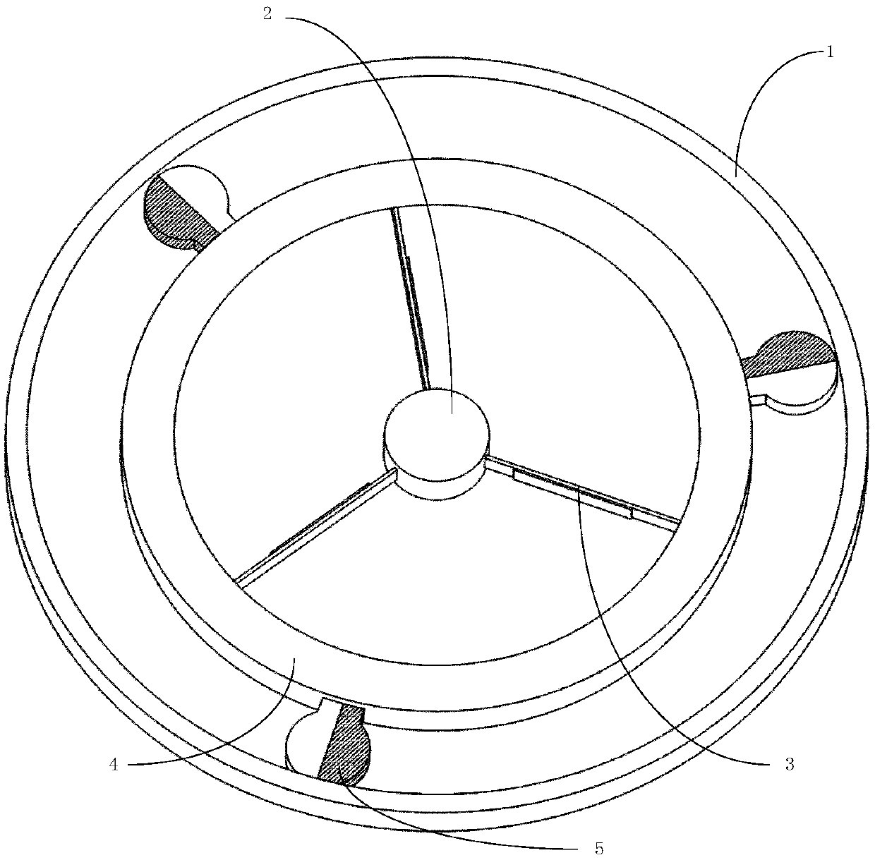
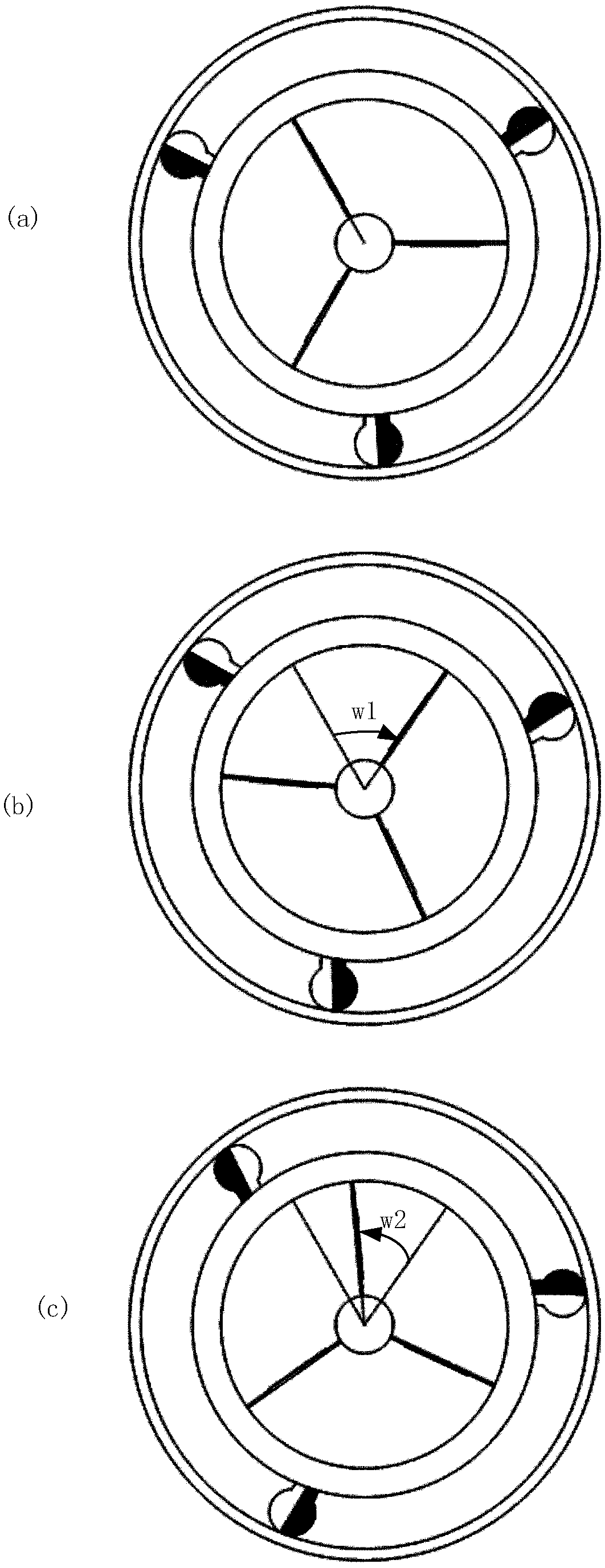
[0010] refer to figure 1 , figure 2 and image 3 , a kind of inertial rotary driver with compound foot support of the present invention is made up of fixed circle 1, central rotating shaft 2, piezoelectric vibrator 3, connection circle 4 and compound foot support 5; Wherein:

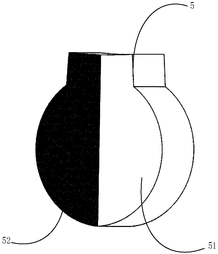
[0011] The fixed circumference 1 is a ring-shaped member, the central rotating shaft 2 is a cylindrical member and can rotate around its axis, the piezoelectric vibrator 3 is formed by pasting a piezoelectric sheet material on a rectangular elastic base, and the connection Circumference 4 is an annular component, and the composite foot support 5 is a cylindrical component composed of low friction coefficient material 51 and high friction coefficient material 52; the fixed circumference 1 is connected with the frame, and the piezoelectric One end of the vibrator 3 is connected to the central rotating shaft 2, and the other end is connected to the connecting circle 4. The composite foot support 5 is eve...


PUM


Abstract

The invention relates to an inertial rotary actuator having a composite foot mount, which includes a fixed circumference, a central rotation shaft, a piezoelectric vibrator, a connecting circumferenceand a composite foot mount, wherein the fixed circumference is connected with a machine frame; one end of the piezoelectric vibrator is connected with the central rotation shaft and the other end isconnected with the connecting circumference; the composite foot mount is uniformly arrange on the outer torus surface of the connecting circumference; and the composite foot mount is in contact with the fixed circumference. When the piezoelectric vibrator is energized, the piezoelectric vibrator vibrates back and forth to drive the central rotating shaft to rotate, and when the piezoelectric vibrator is rotated in different directions, the high friction coefficient material and the low friction coefficient material of the composite foot mount are alternately contacted with the fixed circumference, so that the magnitude of the friction force is changed, and the stepwise directional rotation of the central rotating shaft is realized. The actuator has the advantages of simple structure, easyobtaining of driving signal and simple driving principle, in addition to the advantages of quick response, high precision and no electromagnetic interference of general piezoelectric actuator.

Description

technical field [0001] The invention belongs to the field of piezoelectric drive, and in particular relates to an inertial rotary driver with a composite foot support. Background technique [0002] Piezoelectric drives are mainly divided into piezoelectric ultrasonic motors, clamping piezoelectric drivers, inertial piezoelectric drivers and variable friction piezoelectric drivers. Piezoelectric ultrasonic motors are divided into traveling wave drive and standing wave drive; clamp-type piezoelectric drivers are mainly inchworm-like piezoelectric drivers, and their structures are generally complex and require multiple sets of piezoelectric vibrators; inertial piezoelectric drivers are mainly divided into Impact type and stick-slip type, this type of driver realizes the directional movement of the driver through an asymmetrical driving signal, which has higher requirements on the signal generator; the variable friction piezoelectric driver is mainly divided into variable materi...

Claims


Application Information

Patent Timeline
Patent Type & Authority Applications(China)
IPC IPC(8): H02N2/12
CPCH02N2/12
Inventor 曾祥莉吴越董景石杨志刚李新波刘江伟汪菲菲
Owner JILIN UNIV
Features
  • R&D
  • Intellectual Property
  • Life Sciences
  • Materials
  • Tech Scout
  • Unparalleled Data Quality
  • Higher Quality Content
  • 60% Fewer Hallucinations
Learn More