Filter

A technology of filters and filter components, which is applied in the direction of filtration separation, dispersed particle filtration, chemical instruments and methods, etc., and can solve problems such as dust generation and particle introduction

Inactive Publication Date: 2018-12-28
CHUGAI RO CO LTD
View PDF8 Cites 0 Cited by
  • Summary
  • Abstract
  • Description
  • Claims
  • Application Information

AI Technical Summary

Problems solved by technology

[0003] Here, as shown in Patent Document 2, since the HEPA filter is made of glass fibers and ceramic fibers, dust is generated due to temperature changes, and there is a technique of bringing particles into the heat treatment chamber of the cleaning oven. question

Method used


Image

  • Filter
  • Filter
  • Filter

Examples


Embodiment Construction

[0041] (the whole frame)

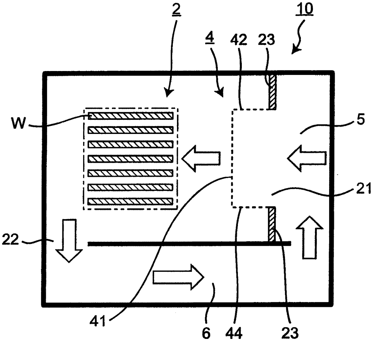
[0042] figure 1 It is a schematic structural diagram of the cleaning oven 10 which concerns on embodiment of this invention. Such as figure 1 As shown, the cleaning oven 10 includes: a heat treatment chamber 2, the heat treatment chamber 2 is configured for heat-treated workpieces W, and has a gas inlet 21 for gas inflow and a gas outlet 22 for gas flow out; filter 4, the above filter 4 passes through Welding is installed on the inner frame 23 forming the gas inlet 21; the space before the filter 5, the space before the filter 5 is used for gas storage before passing through the filter 4; The outgoing gas is sent to the pre-filter space 5. exist figure 1 , the flow of gas is shown by hollow arrows.

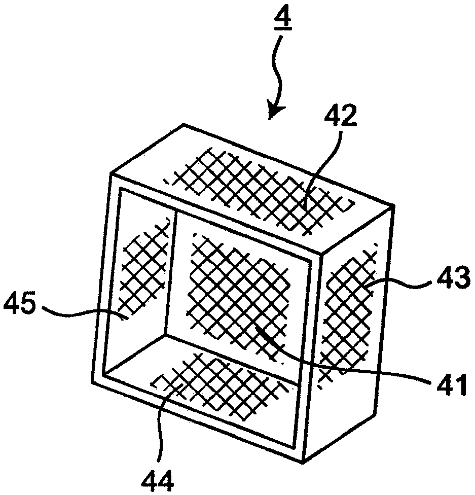
[0043] figure 2 is a schematic perspective view of the filter 4 . Such as figure 1 and figure 2 As shown, the filter 4 includes: a top portion 41 protruding toward the heat treatment chamber 2 side;

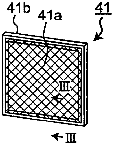
[0044] Figure 3A is a schematic diagram...


PUM


Abstract

A metal filter (4) provided in a clean oven (10) which performs heat treatment of a workpiece by circulating a gas is characterized by being provided with: an apex portion (41) which projects toward aheat treatment chamber (2) in which the workpiece (W) to be heat treated is disposed; and side portions (42 to 45) formed continuously with the apex portion (41).

Description

technical field [0001] The present invention relates to a filter used in a cleaning oven for drying, firing, and the like of semiconductor elements, precision materials, and the like. Background technique [0002] Conventionally, as shown in Patent Document 1, a HEPA filter for removing fine dust (particles) is installed in a cleaning oven. [0003] Here, as shown in Patent Document 2, since the HEPA filter is made of glass fibers and ceramic fibers, dust is generated due to temperature changes, and there is a technique of bringing particles into the heat treatment chamber of the cleaning oven. question. [0004] prior art literature [0005] patent documents [0006] Patent Document 1: Japanese Patent Laid-Open No. 2005-156089 [0007] Patent Document 2: Japanese Patent Laid-Open No. 5-208112 Contents of the invention [0008] The technical problem to be solved by the invention [0009] In addition, Patent Document 2 discloses that a dedicated heater is provided in ...

Claims


Application Information

Patent Timeline
Patent Type & Authority Applications(China)
IPC IPC(8): F24F13/28B01D39/20B01D46/00B01D46/10F24F7/003
CPCB01D39/20B01D46/00B01D46/10B01D46/52F24F7/06F24F13/28F24F7/003B01D39/2027
Inventor 金光和珠池田宗弘
Owner CHUGAI RO CO LTD
Why Eureka
Try Eureka