Eureka AIR delivers breakthrough ideas for toughest innovation challenges, trusted by R&D personnel around the world.

Injection molding device

An injection molding and equipment technology, applied in metal processing equipment, drilling/drilling equipment, clamping, etc., can solve the problems of inability to achieve equidistant drilling operations, difficulty in meeting existing needs, and high use costs

Inactive Publication Date: 2019-01-01
广州市灵汐科技有限公司
View PDF0 Cites 0 Cited by
  • Summary
  • Abstract
  • Description
  • Claims
  • Application Information

AI Technical Summary

Problems solved by technology

[0002] Porous molds are widely used in the field of injection molding. Since these molds often have multiple injection holes, the mold needs to be drilled during production. However, the traditional drilling equipment has a low degree of automation and cannot realize the injection holes on the same circumference. Equidistant drilling operation, there are many drilling equipment with high degree of automation in the existing, but its use cost is relatively high, and the operation is extremely complicated, it is difficult to meet the existing needs, and needs to be improved

Method used


Image

  • Injection molding device
  • Injection molding device

Examples


Embodiment Construction

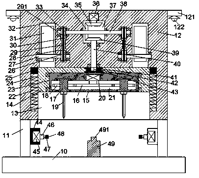
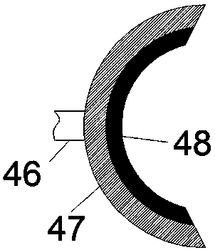
[0015] Such as Figure 1-2 As shown, an injection molding equipment of the present invention includes a base 10, a support column 11 symmetrically arranged on the top end surface of the base 10, and a mounting frame 12 arranged above the support column 11. The mounting frame 12 The bottom end face is provided with a sliding chamber 13 with an opening downward, and a turret 15 is slidably installed in the sliding chamber 13, and a first rotating chamber 23 is arranged in the bottom end face of the turret 15, and the first rotating chamber 23 A turret 15 is rotatably installed through a rotatable bearing, and a second rotating cavity 21 extending left and right is provided in the turret 15, and the inner top wall of the second rotating cavity 21 is fixedly provided with a first motor 20, and the first motor 20 is fixed on the inner top wall of the second rotating cavity 21. The bottom of a motor 20 is power-connected with the first rotating gear 16 located in the second rotating...


PUM


Abstract

The invention discloses an injection molding device. The device comprises a base, supporting columns and a mounting frame arranged above the supporting columns, the supporting columns are arranged onthe end face of the top of the base in a bilateral symmetry manner, a sliding cavity with a downward opening is formed in the bottom end face of the mounting frame, a rotating frame is arranged in thesliding cavity in a sliding manner, a first rotating cavity is formed in the bottom end face of the rotating frame, the first rotating cavity is rotatably provided with a rotating frame through a rotating bearing, a second rotating cavity extending left and right is formed in the rotating frame, a first motor is fixedly arranged on the inner top wall of the second rotating cavity, the bottom of the first motor is in power connection with a first rotating gear located in the second rotating cavity, rotating sleeves in bilateral symmetry are rotatably arranged in the upper and lower end walls of the second rotating cavity through rotating bearings, and second rotating gears engaged with the first rotating gear are fixedly arranged on the rotating sleeve.

Description

technical field [0001] The invention relates to the technical field of injection molding, in particular to an injection molding equipment. Background technique [0002] Porous molds are widely used in the field of injection molding. Since these molds often have multiple injection holes, the mold needs to be drilled during production. However, the traditional drilling equipment has a low degree of automation and cannot realize the injection holes on the same circumference. For the equidistant drilling operation, there are many drilling equipment with a high degree of automation in the present, but the cost of use is relatively high, and the operation is extremely complicated, which is difficult to meet the existing needs and needs to be improved. Contents of the invention [0003] Aiming at the deficiencies of the above technologies, the present invention proposes an injection molding equipment. [0004] The invention is an injection molding equipment, comprising a base, a...

Claims


Application Information

Patent Timeline
Patent Type & Authority Applications(China)
IPC IPC(8): B23B41/00B23B47/00B23Q3/08B23Q5/28B29C33/38
CPCB23B41/00B23B47/00B23Q3/082B23Q5/28B29C33/3842
Inventor 叶翠颖
Owner 广州市灵汐科技有限公司
Why Eureka
Eureka Blog
Learn More