Circuit board manufacturing equipment

A technology for manufacturing equipment and circuit substrates, which is applied in metal processing and other directions, and can solve the problems of high cost of use, complicated operations, and inability to achieve equidistant drilling operations.

Inactive Publication Date: 2018-12-18
广州品帝智能科技有限公司
View PDF0 Cites 0 Cited by
  • Summary
  • Abstract
  • Description
  • Claims
  • Application Information

AI Technical Summary

Problems solved by technology

[0002] With the continuous development of electronic technology, some circuit substrates are widely used in the field of electromechanical. The circuit substrate needs to be drilled in the processing and production. However, the traditional copper clad laminate drilling equipment has a low degree of automation

Method used


Image

  • Circuit board manufacturing equipment
  • Circuit board manufacturing equipment

Examples


Embodiment Construction

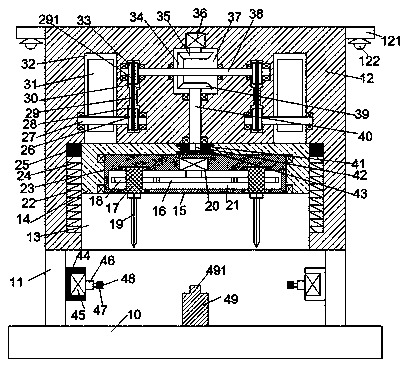
[0015] Such as Figure 1-2 As shown, a circuit substrate manufacturing equipment of the present invention includes a stand 10, a support 11 symmetrically arranged on the top end surface of the stand 10, and an assembly frame 12 arranged above the support 11. The assembly frame 12 The bottom end surface is provided with a sliding joint cavity 13 with the opening downward, and a sliding joint frame 14 is installed in the sliding joint cavity 13. The bottom end surface of the adapter frame 15 is provided with a first transition cavity 23. An adapter chamber 23 is rotatably installed with an adapter frame 15 through a bearing, and the second adapter chamber 21 elongated left and right is provided in the adapter frame 15, and the inner top wall of the second adapter chamber 21 is fixedly installed. There is a first electric rotating machine 20, and the bottom of the first electric rotating machine 20 is connected with the first toothed wheel 16 located in the second transition cavi...


PUM


Abstract

The invention discloses circuit board manufacturing equipment which comprises a frame base, brackets and an assembling frame, wherein the brackets are arranged on the top end surface of the baseplatein a left-right symmetric manner; the assembling frame is arranged on the brackets; a sliding joint cavity of which the through port faces down is arranged in the bottom end surface of the assemblingframe; a sliding joint frame is mounted in the sliding joint cavity in a sliding joint manner; a first rotating joint cavity is arranged in the bottom end surface of a rotating joint frame; the rotating joint frame is rotatably mounted in the first rotating joint cavity through a bearing I; a second rotating joint cavity which extends left and right is arranged in the rotating joint frame; a firstrotating motor is fixedly arranged on the inner top wall of the second rotating joint cavity; a toothed joint wheel which is positioned in the second rotating joint cavity is dynamically connected with the bottom of the first rotating motor; left-right symmetric rotating joint sleeves are rotatably mounted in the upper and lower end walls of the second rotating joint cavity through bearings II; and second toothed joint wheels which are connected with the first toothed joint wheel in a matching manner are fixedly arranged on the rotating joint sleeves.

Description

technical field [0001] The invention relates to the technical field of circuit substrates, in particular to circuit substrate manufacturing equipment. Background technique [0002] With the continuous development of electronic technology, some circuit substrates are widely used in the field of electromechanical. The circuit substrate needs to be drilled in the processing and production. However, the traditional copper clad laminate drilling equipment has a low degree of automation and cannot achieve the same circumference. There are many drilling equipment with a high degree of automation in the existing equipment, but the use cost is relatively large, and the operation is extremely complicated, which is difficult to meet the existing needs and needs to be improved. Contents of the invention [0003] Aiming at the deficiencies of the above technologies, the present invention proposes a circuit substrate manufacturing equipment. [0004] The invention relates to a circuit ...

Claims


Application Information

Patent Timeline
IPC IPC(8): B26F1/16B26D7/26
CPCB26F1/16B26D7/2628
Inventor 方流生
Owner 广州品帝智能科技有限公司
Why Eureka
Try Eureka