Multi-joint robot geometric dimension accuracy calibration device and method based on standard gauge

A technology of multi-joint robots and geometric dimensions, which is applied in manipulators, manufacturing tools, program-controlled manipulators, etc., can solve the problems of affecting detection and correction accuracy, limiting practicability, and high cost

Pending Publication Date: 2019-01-01
YANTAI UNIV
View PDF0 Cites 2 Cited by
  • Summary
  • Abstract
  • Description
  • Claims
  • Application Information

AI Technical Summary

Problems solved by technology

In this process, the error between the detection tool and the robot will be transmitted to the positioning accuracy data at the end of the robot, thus affecting the accuracy of detection and correction, and because the positioning accuracy of the robot is difficult to measure through physical measuring tools, the general detection methods are With the help of high-precision sensors or laser instruments, not only the cost is high, but also due to the complexity of the instrument itself, the measurement process often requires a special laboratory environment and testing personnel to complete, which limits the practicability of such methods
[0003] At present, the most commonly used method in the field of robot error detection and parameter correction is to use high-precision sensors and laser trackers to detect the absolute positioning accuracy of the end, but such equipment is usually expensive and requires professional operators and professional laboratories. , the accuracy of other low-priced equipment cannot be guaranteed
[0004] Another ...

Method used


Image

  • Multi-joint robot geometric dimension accuracy calibration device and method based on standard gauge
  • Multi-joint robot geometric dimension accuracy calibration device and method based on standard gauge
  • Multi-joint robot geometric dimension accuracy calibration device and method based on standard gauge

Examples


Embodiment 1

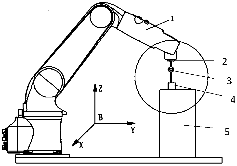
[0082] Taking the KUKA-KR210-2700 robot as an example, the geometric dimension accuracy calibration device of the multi-joint robot manipulator based on the standard measuring tool, the calibration device includes the dial gauge 3 and the standard gauge block 4, the dial gauge 3 and the method at the end of the robot 1 The blue plate 2 is rigidly connected, and the accuracy of the dial indicator 3 is 0.001mm;

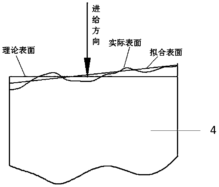
[0083] The standard gauge block 4 is fixed on the workbench 5, and the surface machining accuracy Ra<1.6 of the standard gauge block 4, the geometric dimension (mm) of the standard gauge block 4 is: 100*100*100 (long *Width Height);

[0084] Then, adjust the robot 1 so that the top of the dial indicator 3 fixed on the flange plate 2 at the end of the robot 1 is perpendicular to but not in contact with the surface to be tested of the standard gauge block 4 .

Embodiment 2

[0086] For the installation and commissioning of the calibration device in Embodiment 1, the standard gauge block coordinate system {P} is established with the upper left vertex on the upper surface of the standard gauge block 4 as the coordinate origin, and the standard gauge block 4 is fixed on the workbench 5, Adjust the standard gauge block 4 so that its three coordinate axes are respectively parallel to the X, Y, and Z axes in the robot base coordinate system {B}, wherein the Z axes of the two coordinate systems are opposite to each other,

[0087] Rigidly connect the flange plate 2 at the end of the robot 1 with the digital dial indicator 3, pay attention to the reliable connection to avoid the occurrence of small displacement, fix the standard gauge block 4 on the workbench 5, and adjust the workbench 5 and the standard gauge at the same time. The position of the gauge block 4 makes the three coordinate axes of the standard gauge block coordinate system {P} X, Y, and Z p...

Embodiment 3

[0090] Taking the KUKA-KR210-2700 robot as an example, the method for calibrating the geometric dimension accuracy of the multi-joint robot manipulator based on the standard measuring tool uses the calibration device for the geometric dimension accuracy of the multi-joint robot manipulator based on the standard measuring tool described in Embodiment 1, and includes the following step:

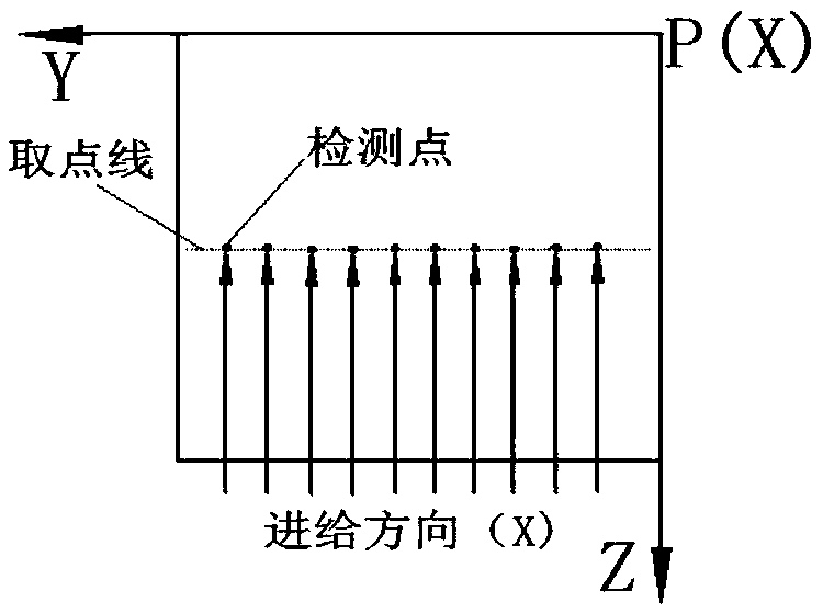
[0091] 1) Take point detection along the point-taking line of feeder X, Y, Z respectively, and determine the reading calculation value x of each detection point on the point-taking line of feeder X, Y, Z i 、y i ,z i (i=1,2,···10) and the calculated value of the rotation angle of each joint axis of the robot [(θ 1 ~θ 6 )i] X , [(θ 1 ~θ 6 )i] Y , [(θ 1 ~θ 6 ) i ] Z (i=1,2,...10);

[0092] Take points on the Y-P-Z surface of the standard gauge block, the point interval is 5mm, take 10 groups of points, feed each point along the X direction for 10 times and take the average value of the...


PUM

PropertyMeasurementUnit
Nominal sizeaaaaaaaaaa

Abstract

The invention relates to a multi-joint robot geometric dimension accuracy calibration device and method based on a standard gauge, and belongs to the technical field of high-precision detection. The multi-joint robot geometric dimension accuracy calibration device comprises a dial indicator and a standard gauge block. The dial indicator is rigidly connected with a flange plate at the tail end of arobot. The standard gauge block is fixed to a workbench. The top end of the dial indicator fixed to the flange plate at the tail end of the robot is perpendicular to a surface to be detected by the standard gauge block, but does not make contact with the surface to be detected by the standard gauge block. The invention further provides a calibration method used for calibrating the geometric dimension of a mechanical arm of a robot through the calibration device. By adoption of the device and method, the simple dial indicator and the simple standard gauge block are used for detecting relativeerrors of the tail end of the robot, so that the influences of accumulative errors are avoided, and changes, caused by variations of the environmental temperature, of the geometric dimension of the robot are compensated; and the method can achieve detection based on analysis in three directions in a three-dimensional spatial coordinate system, so that detection data are more comprehensive.

Description

technical field [0001] This patent relates to a multi-joint robotic arm geometric dimension accuracy calibration device and calibration method based on a standard measuring tool, which belongs to the technical field of high-precision detection. Background technique [0002] At present, the detection and correction of robot positioning accuracy generally adopt the following methods: use laser tracker, infrared sensor and other equipment to track and monitor the end position error of the robot, and use high-definition cameras and other visual detection equipment to detect the end position. Wait. In this process, the error between the detection tool and the robot will be transmitted to the positioning accuracy data at the end of the robot, thus affecting the accuracy of detection and correction, and because the positioning accuracy of the robot is difficult to measure through physical measuring tools, the general detection methods are With the help of high-precision sensors or...

Claims


Application Information

Patent Timeline
IPC IPC(8): B25J9/16
CPCB25J9/1692
Inventor 柴永生李岩牟玲龙殷守民王琦刘希宽岳艳丽
Owner YANTAI UNIV
Why Eureka
Try Eureka