
Track vibration damping device

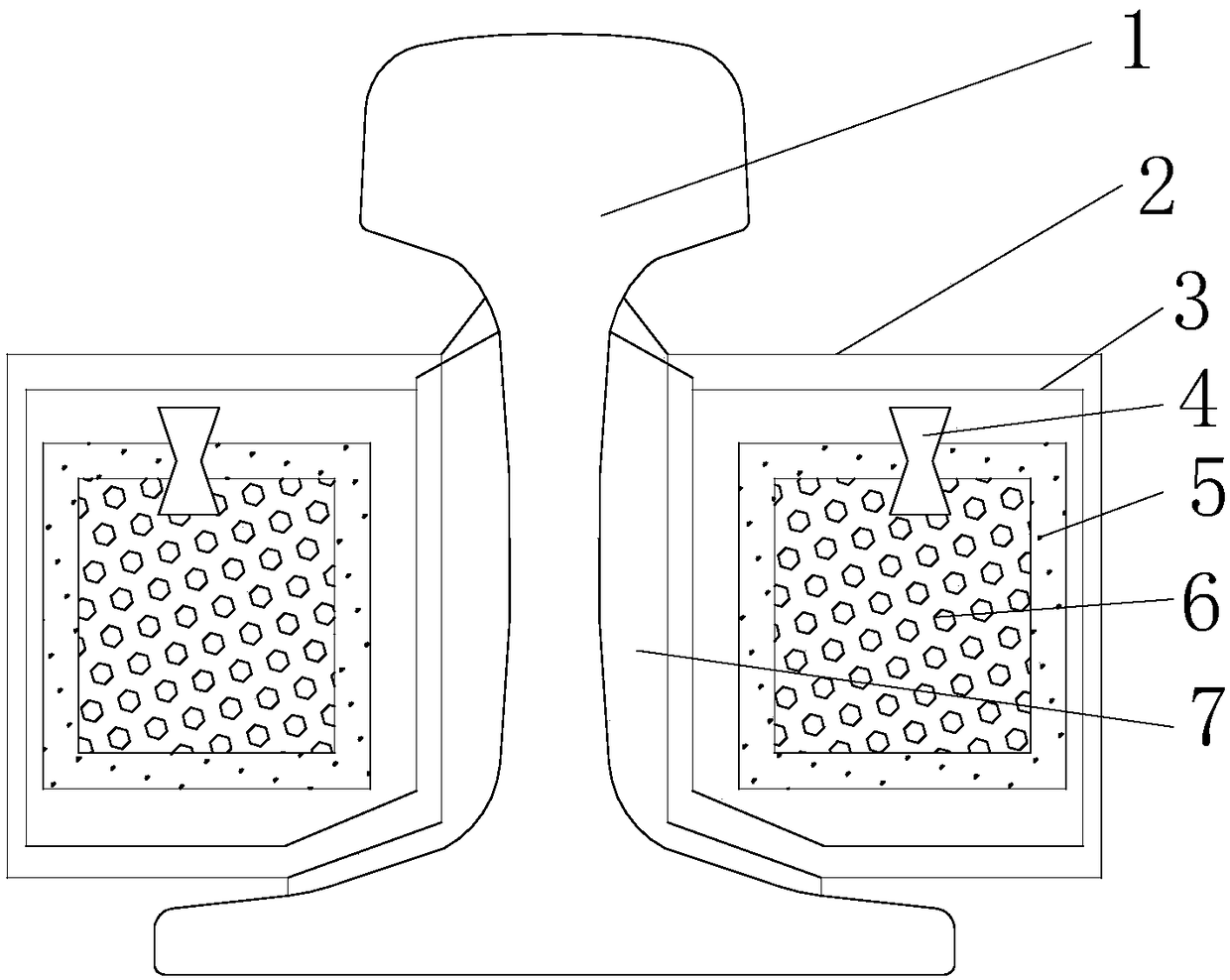
A vibration damping device and rail technology, which is applied in the direction of rails, roads, buildings, etc., can solve the problems of reducing the service life of rails, affecting vibration and noise reduction, accelerating rail wear and other problems, and achieving the effect of reducing rail vibration and adjusting characteristic frequency

Inactive Publication Date: 2019-01-01
BEIJING JIUZHOUYIGUI SHOCK & VIBRATION ISOLATION
View PDF0 Cites 2 Cited by
  • Summary
  • Abstract
  • Description
  • Claims
  • Application Information

AI Technical Summary

Problems solved by technology

However, on the one hand, the vibration reduction effect of the existing constrained damping structure is proportional to the effective working area of ​​the damping material in the structure, and the available non-working surface of the rail is limited, so the vibration reduction effect of this type of technology is greatly restricted On the other hand, the rail head is in direct contact with the wheel, which is the part with the largest vibration amplitude and vibration intensity. However, due to the extremely small size of the non-working surface of the rail head, it is more difficult for the existing restraint damping structure to give an effective response to the vibration of the rail head. Therefore, when the rail is disturbed by the wheels, the deflection phenomenon occurs at the rail head, which accelerates the wear of the rail, and even produces corrugation in severe cases, which affects the entire effect of vibration reduction and noise reduction, reduces the service life of the rail, and improves the track performance. post-maintenance cost

Method used


Image

  • Track vibration damping device
  • Track vibration damping device

Examples


Embodiment 2

[0035] This embodiment is basically the same as Embodiment 1. For brevity of description, in the description of this embodiment, the same technical features as Embodiment 1 will not be described, and only the differences between this embodiment and Embodiment 1:

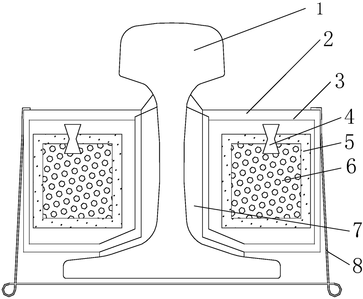
[0036] Such as figure 2 As shown, in this embodiment, the rail vibration damping device further includes an elastic clamp 6 for clamping the vibration damping unit on the steel rail 1 to further ensure a reliable connection between the vibration damping unit and the steel rail 1. Preferably, the number of elastic clamps 6 is multiple, and the plurality of elastic clamps 6 are arranged at intervals along the longitudinal direction of the steel rail 1.

[0037] Specifically, the elastic clip 6 has a U-like structure, and includes two clamping portions and a connecting portion for connecting the two clamping portions. The clamping portions respectively abut against the side of the outer box 2 away from the rail waist. Loca...


PUM


Abstract

The invention relates to the technical field of track transit vibration isolation, and discloses a track vibration damping device including a vibration damping unit mounted between two adjacent fasteners of the track. The vibration damping unit comprises an outer box body which is connected with the track waist of the track and a mass body accommodated in the outer box body, and the gap between the outer box body and the mass body is filled with a damping liquid. The track vibration damping device provided by the invention is characterized in that a vibration damping unit is arranged on the track waist of the track, the vibration damping unit includes an outer case and a mass body accommodated in the outer case, so as to resize the mass, so that the characteristic frequency of the track vibration damping device is matched with the characteristic frequency of the track, so as to reduce the vibration of the track, reduce the noise radiated from the track, and make the internal mass vibrate through the damping liquid filled between the outer box body and the mass body. The damping liquid acts as the dissipation body of energy to consume the vibration energy of the track, so as to adjust the characteristic frequency of the track and reduce the vibration of the track.

Description

Technical field [0001] The invention relates to the technical field of rail transit vibration isolation, in particular to a rail vibration damping device. Background technique [0002] With the development of urbanization in my country, the construction of rail transit has gradually increased. At the same time, with the increase in train speed and traffic density, its impact on the surrounding environment has become more and more serious. Most of the vibration and noise generated by rail transit originate from the interaction between train wheels and rails. When the train passes by, under the interaction of the wheels and rails, the rails and wheels vibrate at the same time, radiating noise outward, and the vibration is transmitted to the tunnel wall and the surrounding soil through the rails, fasteners, and track bed. [0003] At present, in the field of rail transit, the use of free damping or constrained damping treatment on rails, that is, directly laying damping materials on ...

Claims


Application Information

Patent Timeline
IPC IPC(8): E01B19/00
CPCE01B19/003
Inventor 李腾邵斌王欣宇赵文博曾凡冲张厚贵任奇程奕龙
Owner BEIJING JIUZHOUYIGUI SHOCK & VIBRATION ISOLATION
Learn More