Energy storage device for rail transit

An energy storage device and rail transit technology, which is applied in the field of rail transit, can solve problems such as inconvenience, and achieve the effects of improving convenience, high touch efficiency, and preventing interference

Pending Publication Date: 2019-01-01
上海航天智能装备有限公司
View PDF0 Cites 0 Cited by
  • Summary
  • Abstract
  • Description
  • Claims
  • Application Information

AI Technical Summary

Problems solved by technology

If only the PC control method is used, and the rail transit energy storage equip

Method used


Image

  • Energy storage device for rail transit
  • Energy storage device for rail transit

Examples


Example Embodiment

[0024] The present invention will be described in detail below in conjunction with the accompanying drawings and specific embodiments. This embodiment is carried out on the premise of the technical solution of the present invention, and detailed implementation and specific operation process are given, but the protection scope of the present invention is not limited to the following embodiments.

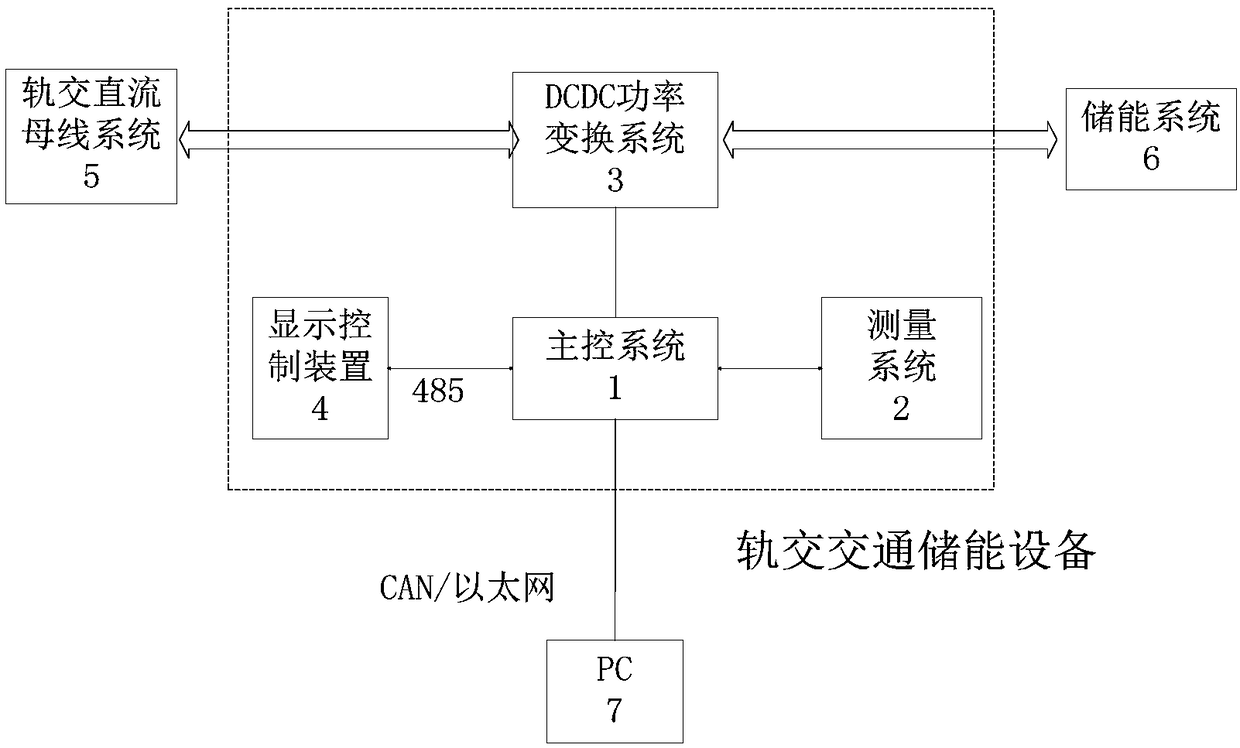
[0025] This embodiment provides a rail transit energy storage device, the structure of which includes a main control system 1, a measurement system 2, a DCDC power conversion system 3, and a display control device 4. The DCDC power conversion system 3 is connected to the rail AC and DC bus system 5 respectively. And the energy storage system 6, the main control system 1 is connected with PC7, and its structural schematic diagram is as follows figure 1 shown.

[0026] The main control system uses DSP as the core MCU, including signal conditioning circuit, auxiliary power supply circui...


PUM


Abstract

The invention relates to an energy storage device for rail transit, comprising a display control device, wherein the display control device comprises a touch screen with a touch-type human-machine interface for displaying an operation menu; the touch-type human-machine interface comprises a touch sensing module for receiving a touch operation signal; the control module is adapted to calculate andcontrol the display content according to the touch operation signal in response to the touch operation signal. Compared with the prior art, the energy storage device of the invention has the advantages of high touch control efficiency, good safety and the like.

Description

technical field [0001] The invention relates to the technical field of rail transit, in particular to a rail transit energy storage device. Background technique [0002] With the development of rail transit vehicle technology, the control mode of rail transit vehicles has changed from a hard-line control mode to a control mode of a dedicated network for rail vehicles. All programmable devices participating in control and monitoring on a rail vehicle are connected through a network bus. Working under the unified scheduling of the network master equipment, each equipment can broadcast its own status information and fault information to the network to realize data sharing, so it can be connected to the rail transit data processing equipment in the rail vehicle dedicated network for rail transit vehicle faults Diagnosis and maintenance are of great significance. [0003] At present, there are two ways to realize the display control part of rail transit energy storage equipment ...

Claims


Application Information

Patent Timeline
IPC IPC(8): G06F3/0488G06F3/0482G06F3/041
CPCG06F3/0412G06F3/0416G06F3/0482G06F3/04886
Inventor 齐凡凡幸宗国
Owner 上海航天智能装备有限公司
Why Eureka
Try Eureka