Electromagnetically operated valve

An electromagnetic drive, electromagnetic coil technology, applied in engine components, machines/engines, charging systems, etc., can solve problems such as discontinuity, and achieve high dynamic strength and easy connection.

Inactive Publication Date: 2002-09-18
ROBERT BOSCH GMBH
View PDF2 Cites 0 Cited by
  • Summary
  • Abstract
  • Description
  • Claims
  • Application Information

AI Technical Summary

Problems solved by technology

Although the laser beam is not attenuated when scanning the slot, the weld may even appear discontinuous in the slot

Method used


Image

  • Electromagnetically operated valve
  • Electromagnetically operated valve
  • Electromagnetically operated valve

Examples


Embodiment Construction

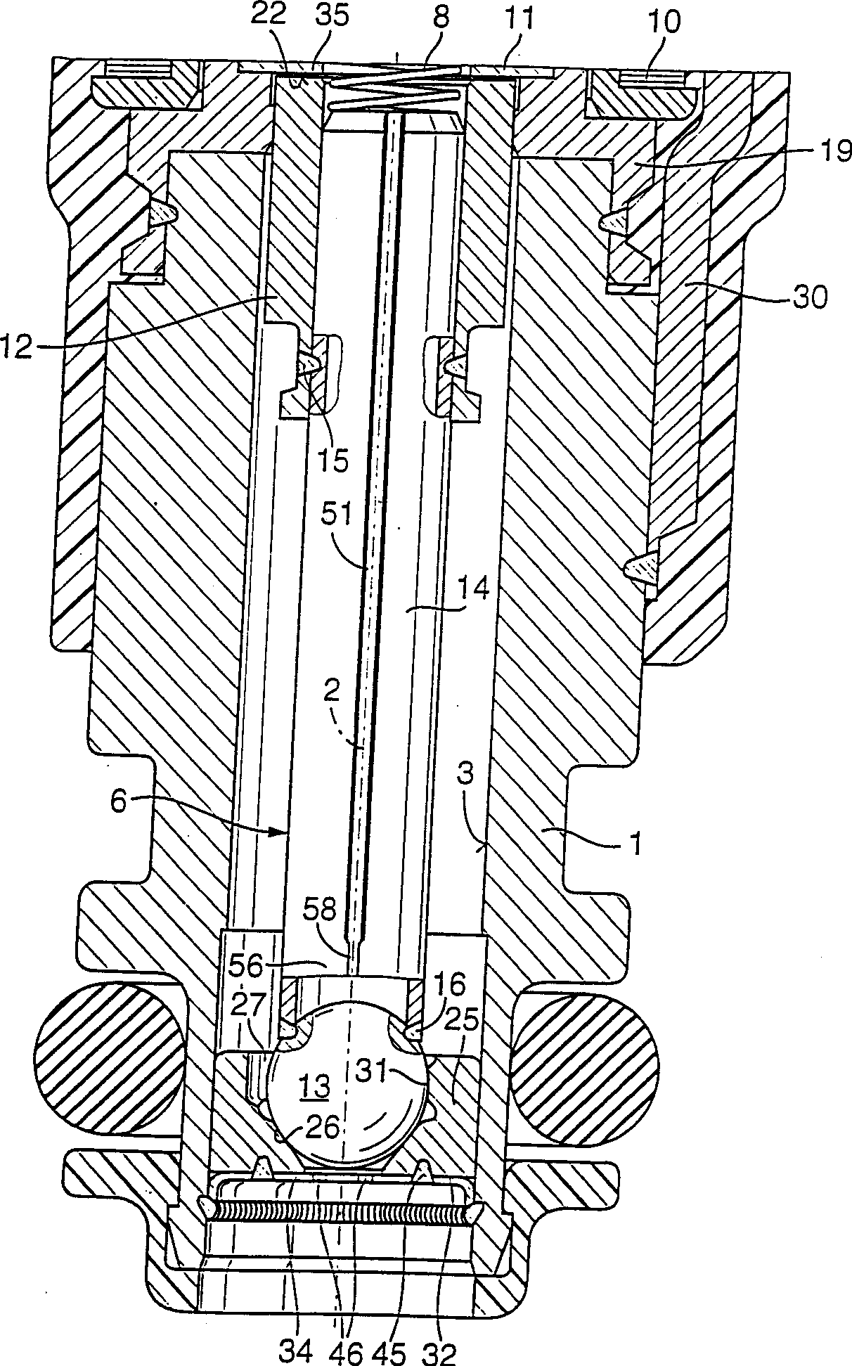
[0015] In FIG. 1 , an electromagnetically actuatable valve in the form of an injection valve of a fuel injection system of a mixture-compressing, forced-ignition internal combustion engine is shown as part of the exemplary embodiment. The valve has a tubular seat carrier 1 in which a longitudinal bore 3 is formed coaxially to the valve longitudinal axis 2 . An axially displaceable valve needle 6 is arranged in the longitudinal bore 3 .

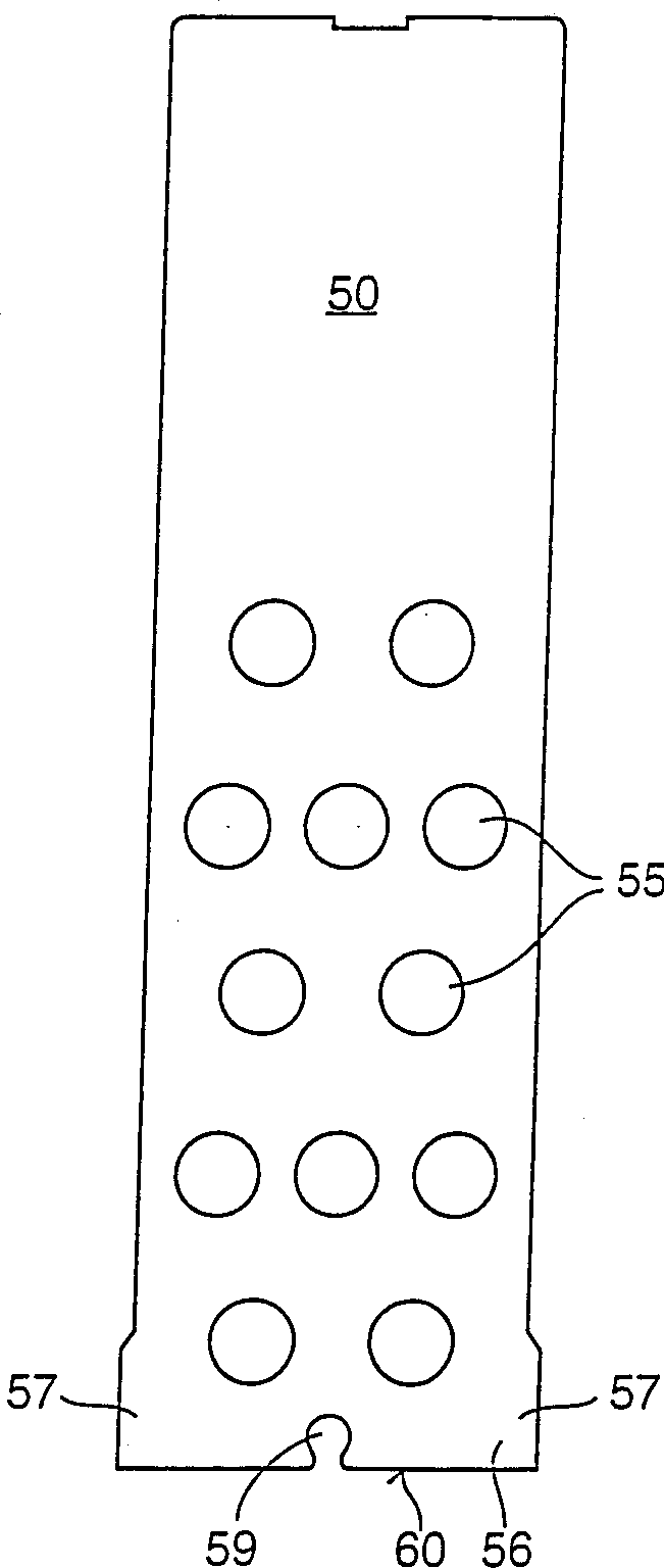
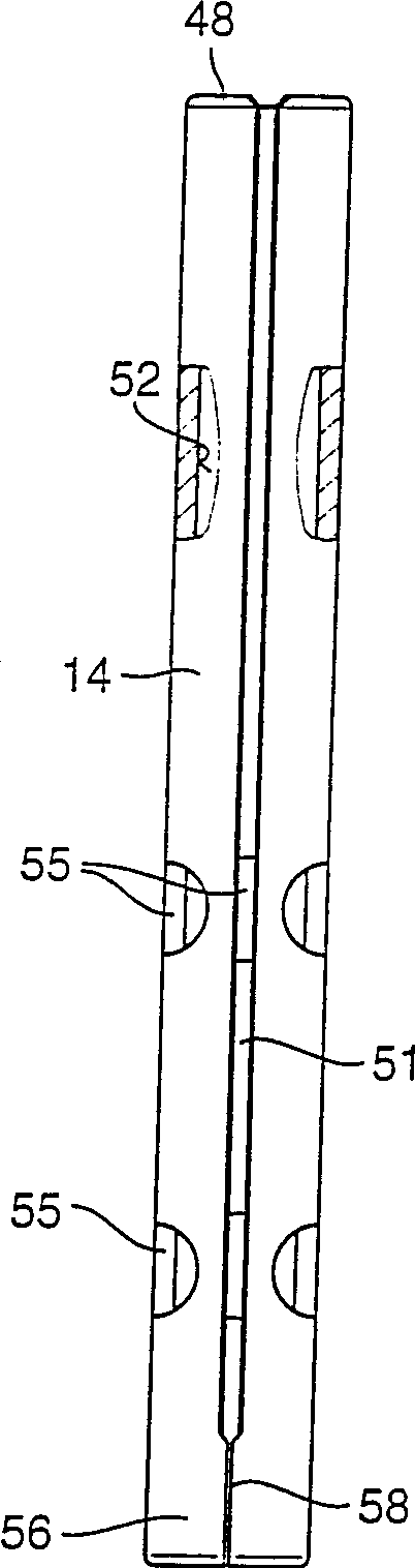
[0016] Solenoid actuation of the valve takes place in a known manner. A solenoid circuit, only partially shown, with a solenoid coil 10 , a core 11 and an armature 12 is used to move the valve needle axially and thus to open or close the valve against the spring force of the return spring 8 . The valve needle 6 consists of an armature 12 , an eg spherical valve closing body 13 and a connecting piece 14 connecting the two parts, wherein the connecting piece 14 has a tubular shape. The return spring 8 bears with its lower end on the upper end ...


PUM


Abstract

Electromagnetically actuatable valve with an axially movable valve needle (6) consisting of an armature (12), a valve closing body (13) and a connecting piece (14) connecting the two parts . The tubular connection (14) has a longitudinally extending slot (51), which has a wider axial extension at its end (56) towards the valve closing body (13) due to the enlargement of the outlet portion of the plate. Small opening width. The valve closing body (13) is fastened very reliably to the lower end (56) of the connecting piece (14) by means of a weld seam (16) while avoiding shrinkage. The valve is especially suitable for fuel injection devices of mixed gas compression and forced ignition internal combustion engines

Description

technical field [0001] The invention relates to an electromagnetically actuatable valve. Background technique [0002] DE-PS 3831196 discloses an electromagnetically actuatable valve which has a valve needle which is axially displaceable in a through-opening of the valve seat holder. The valve needle consists of a cylindrical armature, a spherical valve closing body and a tubular or sleeve-shaped connecting piece connecting the two parts to each other. The connector is made from a flat sheet metal that is rolled or bent in turn until it takes a cylindrical, sleeve-like shape. In this shape, the connecting piece has a slot extending over its entire axial length, which can run either parallel to the longitudinal axis of the valve or at an angle to the longitudinal axis of the valve. The two longitudinally extending end faces of the metal plates used are opposed to the slots formed therein at equidistant intervals. Disadvantageous shrinkage cavities form at relatively wide s...

Claims


Application Information

Patent Timeline
Patent Type & Authority Patents(China)
IPC IPC(8): F02M51/06F02M51/08F02M61/16
CPCF02M51/0682F02M61/168
Inventor 费迪南德·赖特尔迪特尔·迈尔费迪南德·许默
Owner ROBERT BOSCH GMBH
Why Eureka
Try Eureka