Method and system for locating center point of femoral head

A positioning method and positioning system technology, applied in medical science, prosthesis, joint implants, etc., can solve the problem of large positioning error, and achieve the effect of rapid positioning

Active Publication Date: 2019-01-04
SHANGHAI ELECTRICGROUP CORP
View PDF3 Cites 6 Cited by
  • Summary
  • Abstract
  • Description
  • Claims
  • Application Information

AI Technical Summary

Problems solved by technology

[0005] The technical problem to be solved by the present invention is to provide a method and system for positioning the center

Method used


Image

  • Method and system for locating center point of femoral head
  • Method and system for locating center point of femoral head
  • Method and system for locating center point of femoral head

Examples


Embodiment 1

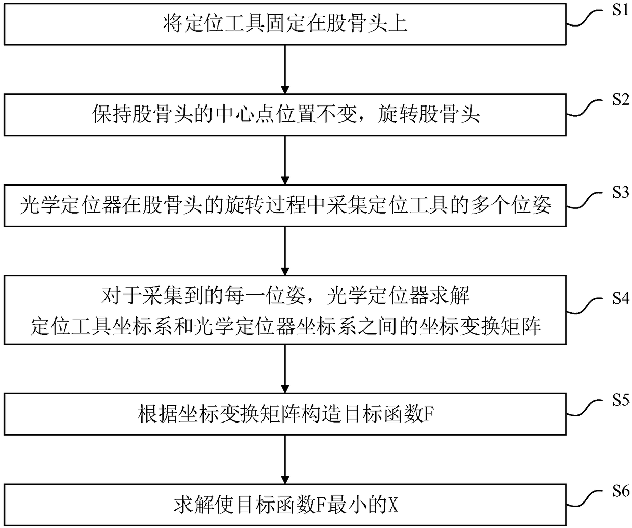
[0045] This embodiment provides a method for positioning the center point of the femoral head, figure 1 A flowchart of this embodiment is shown. see figure 1 , the positioning method of this embodiment includes:

[0046] S1, fixing the positioning tool on the femoral head;

[0047] Before this step, the patient's waist and pelvis can be fixed in the operating bed, and the position of the optical locator can be fixed, wherein the patient's thigh (femoral head) is guaranteed to be within the tracking range of the optical locator.

[0048] In this step, the positioning tool can be fixed on the distal end of the femoral head relative to the central point. Specifically, in this embodiment, a bone nail can be driven into a position about 10 cm away from the knee joint to install the positioning tool.

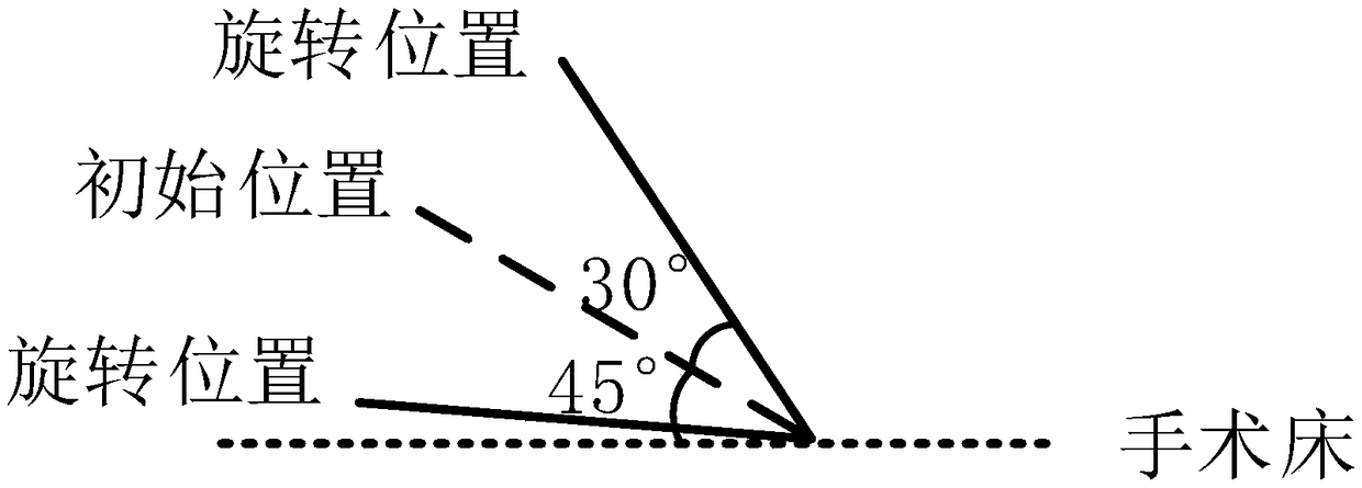
[0049] S2. Keep the central position of the femoral head unchanged, and rotate the femoral head;

[0050] In this step, the position of the center point is kept unchanged, that is...

Embodiment 2

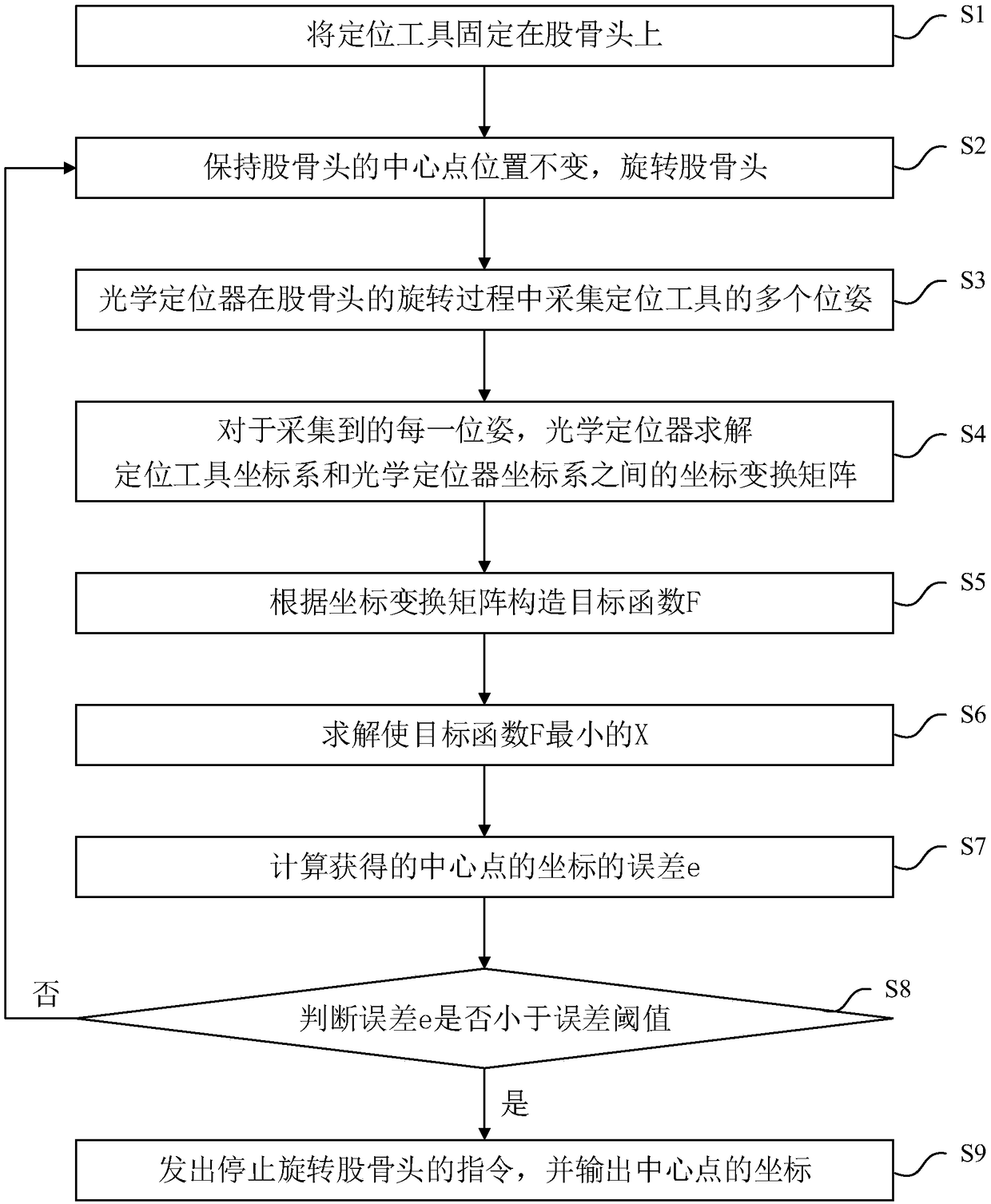
[0087] This embodiment is a further improvement to Embodiment 1, see image 3 The improvement of the positioning method of this embodiment compared with Embodiment 1 is that after step S6, the positioning method of this embodiment further includes:

[0088] S7. Calculate the error e of the coordinates of the center point;

[0089] This step can be used to evaluate the center point positioning accuracy of the femoral head, specifically,

[0090]

[0091] Expand the above formula to get:

[0092]

[0093] Table 1 shows 10 sets of experimental records for locating the center point of the femoral head when the position of the optical locator remains unchanged, that is, the coordinate transformation relationship between the coordinate system of the positioning tool and the coordinate system of the optical locator remains unchanged.

[0094] Table I

[0095]

[0096] The smaller the error e is, the more accurate the position of the center point of the femoral head is obt...

Embodiment 3

[0105] This embodiment provides a positioning system for the center point of the femoral head, Figure 4 A schematic diagram of the modules of this embodiment is shown. see Figure 4 , the positioning system of this embodiment includes a positioning tool 1 , an optical positioner 2 , an objective function construction module 3 , and a central point coordinate solution module 4 .

[0106] The positioning tool 1 is used for fixing on the femoral head. Specifically, the positioning tool 1 can be fixed on the distal end of the femoral head relative to the central point. Specifically, in this embodiment, the bone nail can be nailed at a position about 10 cm away from the knee joint to install the positioning tool 1 .

[0107] The optical positioner 2 is used to collect multiple poses of the positioning tool 1 during the process of rotating the femoral head. Wherein, the position of the center point of the femoral head remains unchanged during the rotation process, that is, in th...


PUM


Abstract

The invention discloses a method and a system for locating a center point of a femoral head. The positioning method comprises the following steps: fixing the positioning tool on the femoral head; keeping the center of the femoral head unchanged and rotating the femoral head. The optical positioner collects multiple positions and postures of the positioning tool during the rotation of the femoral head. For each posture collected, the coordinate transformation matrix between the coordinate system of the positioning tool and the coordinate system of the optical positioner is solved by optical positioner. A target function F is constructed according to a coordinate transformation matrix, to obtain the coordinates of the center point in the positioning tool coordinate system by solving the X which minimizes the objective function F. Thus, the invention can easily and quickly realize the positioning of the center of the femoral head.

Description

technical field [0001] The invention relates to the technical field of computer-aided medical treatment, in particular to a positioning method and system for the central point of a femoral head. Background technique [0002] With the continuous progress of modern medicine and the wide application of advanced achievements in various disciplines in medicine, surgical operations have made great progress in reducing patient pain and surgical incisions, and research on minimally invasive and painless surgical operations is also in full swing. . Hip and knee replacement operations are relatively complicated surgical operations. Although modern joint replacement operations are assisted by advanced computer imaging technology and optical positioning technology, the safety of the operation has been greatly improved, and minimally invasiveness has also been achieved. There must be a breakthrough, but the error in the positioning of the center of the femoral head during the operation ...

Claims


Application Information

Patent Timeline
IPC IPC(8): A61F2/46
CPCA61F2/4657
Inventor 李攀叶震李晓静严日明
Owner SHANGHAI ELECTRICGROUP CORP
Why Eureka
Try Eureka