Pouring device for polyurethane rubber production

A polyurethane rubber, pouring box technology, applied in the direction of spring/shock absorber, vibration suppression adjustment, mechanical equipment, etc., can solve the problems of equipment vibration, equipment loud noise, affecting the working environment of the device, etc., to increase work efficiency and improve work. The effect of environment and convenient positioning

Pending Publication Date: 2022-04-12
张革初
View PDF0 Cites 0 Cited by
  • Summary
  • Abstract
  • Description
  • Claims
  • Application Information

AI Technical Summary

Problems solved by technology

[0005] The invention provides a pouring device for the production of polyurethane rubber. One of the purposes is to have the function of shock absorption and noise reduction, so as to solve the problem that the pouring device is easy to cause equipment vibration when stamping, causing the equipment to generate relatively large noise, thereby affecting the operation of the device. Environmental problems; another purpose is to solve the problem of affecting the working efficiency of the device because the pouring parts are not easy to take out when the pouring equipment is pouring, so as to achieve the effect of ejection function

Method used


Image

  • Pouring device for polyurethane rubber production
  • Pouring device for polyurethane rubber production
  • Pouring device for polyurethane rubber production

Examples


Embodiment 1

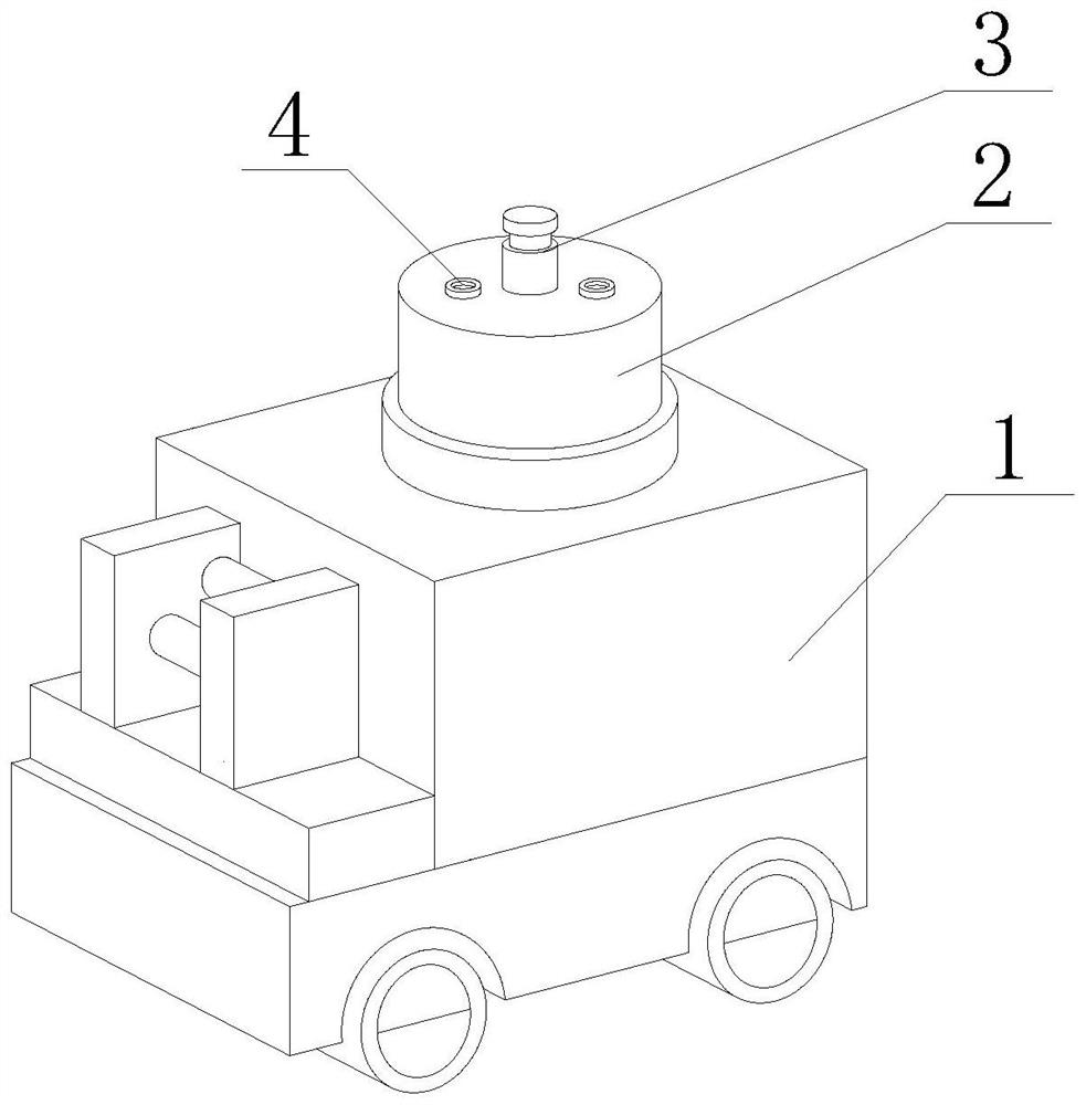
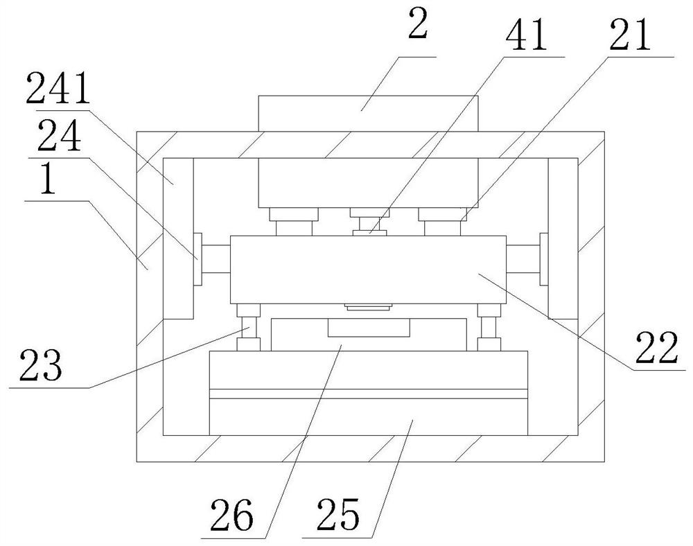
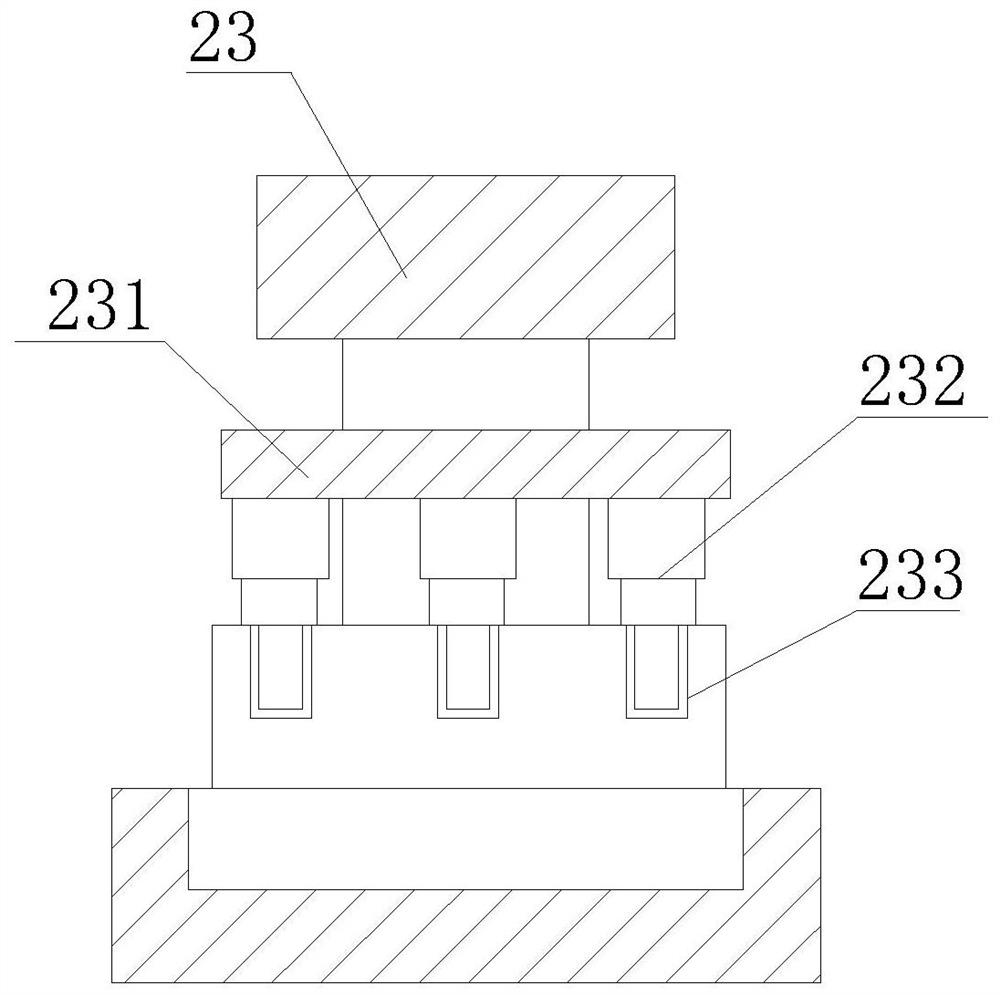
[0034] Such as Figure 1-8 As shown, the present invention provides a pouring device for polyurethane rubber production, comprising a pouring box main body 1, a stamping pipe 2, a stamping pump 3 and a feeding port 4, the top of the pouring box main body 1 is provided with a stamping pipe 2, and the stamping pipe 2 A stamping pump 3 is fixedly installed on the top of the stamping pump 3, and a feeding port 4 is provided on both sides of the stamping pump 3. The bottom of the stamping tube 2 is provided with a connecting column 21, and the bottom of the connecting column 21 is provided with an upper mold 22. The side is provided with stamping column 23, and the bottom of stamping column 23 is provided with pouring mold 25, and the outer side of stamping column 23 is provided with limit ring 231, and the bottom of limit ring 231 is fixedly installed with buffer column 232, and the bottom of buffer column 232 is provided with buffer block, the top of the buffer block has a buffer...

Embodiment 2

[0037] Such as Figure 1-8 As shown, on the basis of Embodiment 1, the present invention provides a technical solution: preferably, both sides of the upper mold 22 are fixedly connected with slide bars 24, and the sides of the slide bar 24 are movably sleeved with slide rails 241, and the slide rails The other side of 241 is fixedly installed in the inner side of pouring box main body 1.

[0038] In this embodiment, when the upper mold 22 is moving and stamping, the slide bar 24 is driven to move, so that the slide bar 24 moves on the slide rail 241, and then the stamping column 23 is used to limit and fix the position to achieve the stamping positioning of the mold. Function, convenient and convenient positioning of the device.

Embodiment 3

[0040] Such as Figure 1-8 Shown, on the basis of embodiment 1, the present invention provides a kind of technical scheme: preferably, the top of pouring mold 25 is fixedly installed with pouring block 26, and the top of pouring block 26 is provided with pouring groove 261, and pouring groove 261 inner cavity The bottom of the ejector plate 262 is provided with an ejector mechanism, and the ejector mechanism includes a lifting column 2621. Sliding column 2622, fixed block 2626 is fixedly installed on both sides of sliding column 2622, one side of fixed block 2626 is fixedly connected with moving bar 2624, the other end of moving bar 2624 is provided with moving block 2623, and the top of moving block 2623 is fixedly installed with Push rod 2625, the push rod 2625 is arranged at the bottom of the ejector plate 262, heating blocks 263 are arranged on both sides of the pouring groove 261, and a heating net 2631 is arranged inside the heating block 263, and the two ends of the hea...


PUM


Abstract

The invention discloses a pouring device for polyurethane rubber production, and relates to the technical field of pouring devices, the pouring device comprises a pouring box main body, a punching pipe, a punching pump and a feeding port, the top of the pouring box main body is provided with the punching pipe, and the top of the punching pipe is fixedly provided with the punching pump. A pouring piece is stamped in the pouring groove, a base is connected to a power source in a matched mode, a heating net is powered on for heating, then a heating plate and heating holes are matched with each other, internal heat is transferred, the function of heating the interior of the pouring groove is achieved, and the preheating function of the device is facilitated; and then a movable rod telescopically moves to drive a movable block to slide on the outer side of a sliding column, so that a push rod is pushed to adjust the angle, the two sides of the bottom of the ejection plate are pushed, the effect of improving the stability of the ejection plate is achieved, the problem that a pouring part is inconvenient to take out is solved, the pouring part can be conveniently ejected by the device, and the convenience of the device is improved.

Description

technical field [0001] The invention relates to the technical field of pouring devices, in particular to a pouring device for polyurethane rubber production. Background technique [0002] Polyurethane rubber is a series of elastomer materials containing more carbamate groups on the main chain of the polymer. The traditional classification of polyurethane elastomers is divided according to the processing method, which is divided into cast polyurethane elastomers and mixing polyurethane elastomers. Elastomer and thermoplastic polyurethane elastomer. During the use of the existing pouring device for polyurethane rubber production, it is generally necessary to place the mold on the slide plate, then position the mold and transport it to the lower end of the pouring head, and then use the pouring head to Pouring in molds. There are following problems at prior art: [0003] 1. When the pouring device is stamping, it is easy to cause vibration of the equipment, causing the equipm...

Claims


Application Information

Patent Timeline
Patent Type & Authority Applications(China)
IPC IPC(8): B29C39/02B29C39/26B29C39/22B29C39/36B29C39/38F16F15/023F16F15/04F16F15/06
Inventor 张革初
Owner 张革初
Why Eureka
Try Eureka