Mounting bracket for mounting monitoring camera

A technology for monitoring cameras and mounting brackets, applied in the directions of machines/brackets, supporting machines, mechanical equipment, etc., can solve the problems of reducing the firmness of the connections of the mounting brackets, affecting the normal use of monitoring cameras, affecting the convenience of monitoring cameras, etc. Achieve the effect of increasing stability, convenient and convenient use, and increasing the performance of clamping and fixing

Pending Publication Date: 2022-05-10
浙江数衍数据科技有限公司
View PDF20 Cites 0 Cited by
  • Summary
  • Abstract
  • Description
  • Claims
  • Application Information

AI Technical Summary

Problems solved by technology

[0005] The invention provides a mounting bracket for installing a monitoring camera, one of which is to have the function of increasing the fixity, and solve the problem of the long-term use of the monitoring camera, which leads to a decrease in the firmness of the connection of the mounting bracket. , easy to shake and affect the normal use of the surveillance camera; another purpose is to solve the problem that the traditional surveillance camera is not easy to adjust the angle, making the monitoring range limited, which affects the convenience of the surveillance camera, so as to achieve convenient adjustment The function of the angle, the effect of convenient device and convenient use

Method used


Image

  • Mounting bracket for mounting monitoring camera
  • Mounting bracket for mounting monitoring camera
  • Mounting bracket for mounting monitoring camera

Examples


Embodiment 1

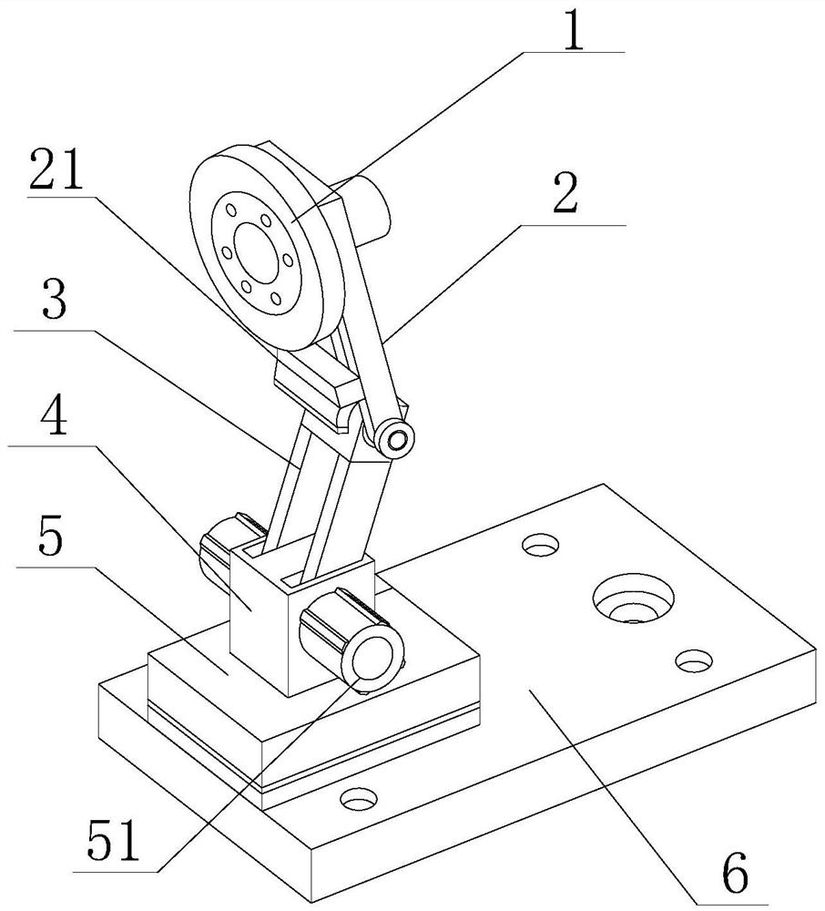
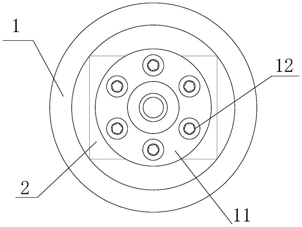
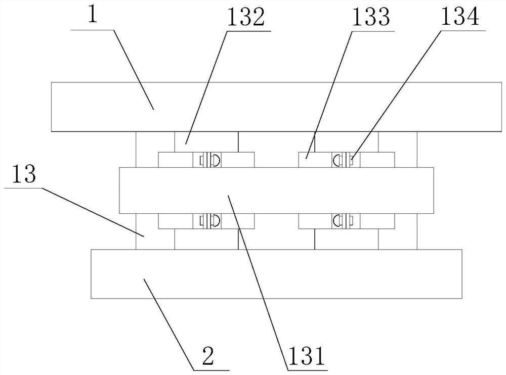
[0032] Such as Figure 1-7 As shown, the present invention provides a mounting bracket for installing a monitoring camera, including a mounting plate 1, a first support 2, a second support 3, an adjustment block 4, and a fixed base 5, and the side of the mounting plate 1 is fixedly connected with a connection Column 13, the other end of connecting column 13 is provided with first support 2, and the bottom of first support 2 is movably installed with second support 3, and the bottom of second support 3 is provided with adjustment block 4, and the both sides of adjustment block 4 are provided with The adjustment shaft 51, the bottom of the adjustment block 4 is fixedly equipped with a fixed base 5, the bottom of the fixed base 5 is provided with an installation base plate 6, one side of the top of the first bracket 2 is provided with a fixed block 11, and the side of the fixed block 11 is threadedly connected with a fixed Bolt 12, one end of the fixing bolt 12 extends to the ins...

Embodiment 2

[0035] Such as Figure 1-7As shown, on the basis of Embodiment 1, the present invention provides a technical solution: preferably, the side of the first bracket 2 is fixedly equipped with a telescopic block 21, and the bottom of the telescopic block 21 is fixedly installed with an adjustment plate 22, and the adjustment plate 22 There are chute 23 on both sides of the chute 23, a sliding column 24 is arranged inside the chute 23, an extension plate 25 is fixedly installed on the bottom of the sliding column 24, and a pressing pad 26 is arranged on one side of the bottom of the extension plate 25, and the two sides of the sliding column 24 A limiting plate 271 is arranged on one side, and a friction scraper 272 is fixedly installed on one side of the limiting plate 271 close to the sliding column 24 , and a pushing column 27 is fixedly installed on the other side of the limiting plate 271 .

[0036] In this embodiment, through the mutual cooperation of the first bracket 2 and t...

Embodiment 3

[0038] Such as Figure 1-7 As shown, on the basis of Embodiment 1, the present invention provides a technical solution: preferably, the bottom of the installation base plate 6 is provided with an installation groove 61, and the inside of the installation groove 61 is provided with a clamping bolt 52, and the clamping bolt 52 The top is threadedly connected to the bottom of the fixed base 5, one end of the mounting groove 61 is provided with a clamping groove 62, and the end of the mounting groove 61 far away from the clamping groove 62 is fixedly installed with a fixed shaft 63, and the outer side of the fixed shaft 63 is movably mounted with a sealing plate 64 , One side of the top of the sealing plate 64 is provided with a locking block 641 .

[0039] In this embodiment, the clamping bolt 52 is threadedly connected to the bottom of the fixed base 5, which facilitates the fixed base 5 to be fixedly installed on the installation base 6, so that the sealing plate 64 rotates out...


PUM


Abstract

The invention discloses a mounting bracket for mounting a monitoring camera, and relates to the technical field of monitoring equipment, the mounting bracket comprises a mounting disc, a first bracket, a second bracket, an adjusting block and a fixed base, the side surface of the mounting disc is fixedly connected with a connecting column, and the other end of the connecting column is provided with the first bracket. Through mutual cooperation of the first support and the second support, rotation adjustment is conducted on the joint of the first support and the second support, when the joint is adjusted to a proper position, a sliding column is moved, an extension plate is driven to move downwards, a pressing pad abuts against the side face of the second support, then a pushing and pressing column is pressed, and a limiting plate is driven to extrude and fix the sliding column; and meanwhile, the friction force of a friction scraper is utilized, the clamping and fixing performance is improved, the sliding column is conveniently fixed and limited, the adjusting function is achieved, the problems that a traditional monitoring camera is inconvenient to adjust the angle, and the monitoring range is limited are solved, the adjusting function is added to the mounting bracket, and therefore the device is convenient to use.

Description

technical field [0001] The invention relates to the technical field of monitoring equipment, in particular to a mounting bracket for installing a monitoring camera. Background technique [0002] Monitor refers to the general term for recording and storing video and audio signals by using camera storage devices. With the increasing popularity of closed-circuit monitoring in civil and commercial purposes, surveillance cameras are widely used in various fields to play a role in enterprise management and social security. For the role of escort, monitors are widely used in residential buildings, real estate villas, shopping malls, stores, and financial offices. Each different application field requires different types of monitors. There are following problems at prior art: [0003] 1. The surveillance camera is used for a long time, which leads to the reduction of the firmness of the connection of the mounting bracket. Under the action of external wind, it is easy to shake, whic...

Claims


Application Information

Patent Timeline
Patent Type & Authority Applications(China)
IPC IPC(8): F16M11/04F16M11/20F16M11/24F16M13/02F16F15/08H04N5/225
CPCF16M11/04F16M11/2021F16M11/24F16M13/02F16F15/085F16M2200/04F16M2200/022F16F2238/026H04N23/50
Inventor 沈景亮
Owner 浙江数衍数据科技有限公司
Why Eureka
Try Eureka