Pressure water tank for water conservancy project drainage station

A pressurized water tank and water conservancy engineering technology, applied in water conservancy projects, water conservancy engineering equipment, water conservation, etc., can solve the problems of reduced service life of the pressurized water tank, poor protection performance of the pressurized water tank, poor sealing of the pressurized water tank, etc., to achieve improved sealing, The effect of increasing the sealing effect and improving the sealing performance

Pending Publication Date: 2022-05-17
刘俊
View PDF0 Cites 0 Cited by
  • Summary
  • Abstract
  • Description
  • Claims
  • Application Information

AI Technical Summary

Problems solved by technology

[0005] The invention provides a pressurized water tank for drainage stations of water conservancy projects, one purpose of which is to have the function of increasing the sealing performance and solve the problem that the poor sealing performance of the pressurized water tank easily leads to internal air pressure leakage, thereby affecting the convenient use of the device; wherein Another purpose is to solve the problem that the protection performance of the pressure water tank is poor, and it is easy to damage the valve port under the influence of external force, resulting in the reduction of the service life of the pressure water tank, so as to increase the strength and improve the protection function of the device.

Method used


Image

  • Pressure water tank for water conservancy project drainage station
  • Pressure water tank for water conservancy project drainage station
  • Pressure water tank for water conservancy project drainage station

Examples


Embodiment 1

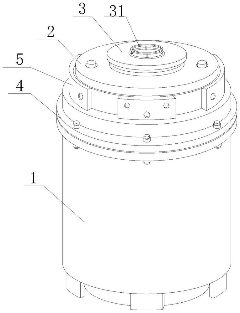
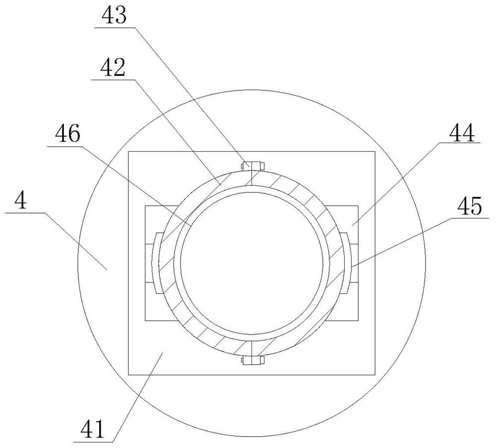
[0042] Such as Figure 1-8 As shown, the present invention provides a pressure water tank for drainage stations of water conservancy projects, comprising a water tank main body 1, a sealing top cover 2, a valve 3 and a sealing flange 4, the top of the water tank main body 1 is threadedly connected with a sealing flange 4, and the sealing method The top of the blue 4 is fixedly installed with a sealing top cover 2, and the top of the sealing top cover 2 is provided with a valve 3, and the top of the valve 3 is fixedly installed with a turret 31, and the outer side of the sealing top cover 2 is fixedly sleeved with a limit ring 51, and the limit The outer side of the ring 51 is provided with a socket groove 52, the inside of the socket groove 52 is movably socketed with a protective baffle 5, the inner side of the sealing flange 4 is fixedly installed with a mounting plate 41, and the inside of the mounting plate 41 is provided with a nozzle, and the mounting plate The top of 41...

Embodiment 2

[0045] Such as Figure 1-8 As shown, on the basis of Embodiment 1, the present invention provides a technical solution: preferably, the side of the sealing block 42 is provided with a draw-in groove, and the inside of the draw-in groove is fixedly equipped with a sealing gasket 421, and the side movable sleeve of the sealing gasket 421 A sealing plate 46 is connected, and a moisture-proof plate 461 is fixedly installed on the bottom of the sealing plate 46 , and a sealing film 462 is fixedly installed on the bottom of the moisture-proof plate 461 .

[0046] In this embodiment, the sealing gasket 421 is installed inside the card slot, and the sealing gasket 421 is utilized for its good sealing properties, so that when the sealing plate 46 is installed inside the card slot, the sealing performance of the joint is increased, and then the sealing film 462 cooperates with the moisture-proof plate 461 to further seal the valve port of the water tank main body 1 by utilizing the tigh...

Embodiment 3

[0048] Such as Figure 1-8 As shown, on the basis of Embodiment 1, the present invention provides a technical solution: preferably, a push block 53 is fixedly installed on the side of the protective baffle 5, and a pressing pad 532 is fixedly installed on the top of the pushing block 53, and the pressing pad 532 A pressing plate 531 is fixedly installed on the top of the pressing pad 532, and pressing blocks 5321 are arranged on both sides of the inner cavity of the pressing pad 532. A buffer column 5322 is fixedly installed on the inner side of the pressing block 5321, and a pressing column 5311 is arranged inside the pressing plate 531. The bottom of the telescopic bullet column 5312 is provided with a pressing base 5313 fixedly mounted on the bottom of the telescopic bullet column 5312, and an airbag cushion 5314 is fixedly installed inside the pressing base 5313.

[0049] In this embodiment, the protective baffle 5 and the limit ring 51 are sleeved on the outer side of the...


PUM


Abstract

The invention discloses a pressure water tank for a water conservancy project drainage station, and relates to the technical field of water conservancy project equipment, the pressure water tank comprises a water tank main body, a sealing top cover, a valve and a sealing flange, the top of the water tank main body is in threaded connection with the sealing flange, the sealing top cover is fixedly mounted at the top of the sealing flange, and the valve is arranged at the top of the sealing top cover. When the outer side of a sealing top cover is subjected to extrusion acting force, a pressing plate is matched to press a telescopic pressing column, and an air bag cushion is compressed, so that internal air pressure moves towards the two sides, a stretching rod is pushed to move, and therefore a sleeving plate is pushed from bottom to top to move upwards, and the sleeving plate drives a springback column to stretch while ascending; the acting force is buffered and consumed through the elasticity of stretching of the rebound columns, the buffering protection function is achieved, the problems that the protection performance of the pressure water tank is poor, and a valve opening is prone to being damaged under the influence of external force are solved, the protection function of the device is increased, and the service life of the device is prolonged.

Description

technical field [0001] The invention relates to the technical field of water conservancy engineering equipment, in particular to a pressure water tank for waterlogging stations of water conservancy projects. Background technique [0002] Water conservancy projects are projects built to control and allocate natural surface water and groundwater to achieve the purpose of eliminating harm and rejuvenating profits. Also known as water engineering. Water is an indispensable precious resource for human production and life, but its natural state does not fully meet human needs. Only by building water conservancy projects can we control water flow, prevent floods, and regulate and distribute water to meet the needs of people's life and production for water resources. Water conservancy projects need to build different types of hydraulic structures such as dams, dikes, spillways, sluices, water inlets, channels, canals, rafts, and fishways to achieve their goals. There are followin...

Claims


Application Information

Patent Timeline
IPC IPC(8): E02B1/00E03F5/00E03F7/02B65D90/00B65D90/08B65D90/12B65D90/52
CPCE02B1/00E03F5/00E03F7/02B65D90/00B65D90/08B65D90/12B65D90/52Y02A20/00
Inventor 刘俊
Owner 刘俊
Why Eureka
Try Eureka