Rapid detection die for automotive trim finished product

A technology for detecting molds and automotive interiors, applied to household appliances, other household appliances, household components, etc., can solve the problems of cumbersome connections, increased difficulty of disassembly, and increased manual labor, so as to improve safety performance, increase work efficiency, The effect of increasing cushioning

Pending Publication Date: 2022-05-06
浙江德清中博机械有限公司
View PDF0 Cites 0 Cited by
  • Summary
  • Abstract
  • Description
  • Claims
  • Application Information

AI Technical Summary

Problems solved by technology

[0005] The present invention provides a quick detection mold for finished automobile interior decoration, one of the purpose is to have the function of convenient disassembly, and solve the phenomenon that when the device needs to be disassembled, cleaned or replaced, it is difficult to disassemble due to cumbersome connections, resulting in A lot of time is wasted during disassembly, which increases the difficulty of disassembly and reduces the work efficiency; another purpose is to solve the problem of internal adhesion residues in the detection mold groove during detection of the detection mold, which requires manual work. Clean up the residue, causing the problem of increased manual labor, in order to achieve the effect of convenient cleaning

Method used


Image

  • Rapid detection die for automotive trim finished product
  • Rapid detection die for automotive trim finished product
  • Rapid detection die for automotive trim finished product

Examples


Embodiment 1

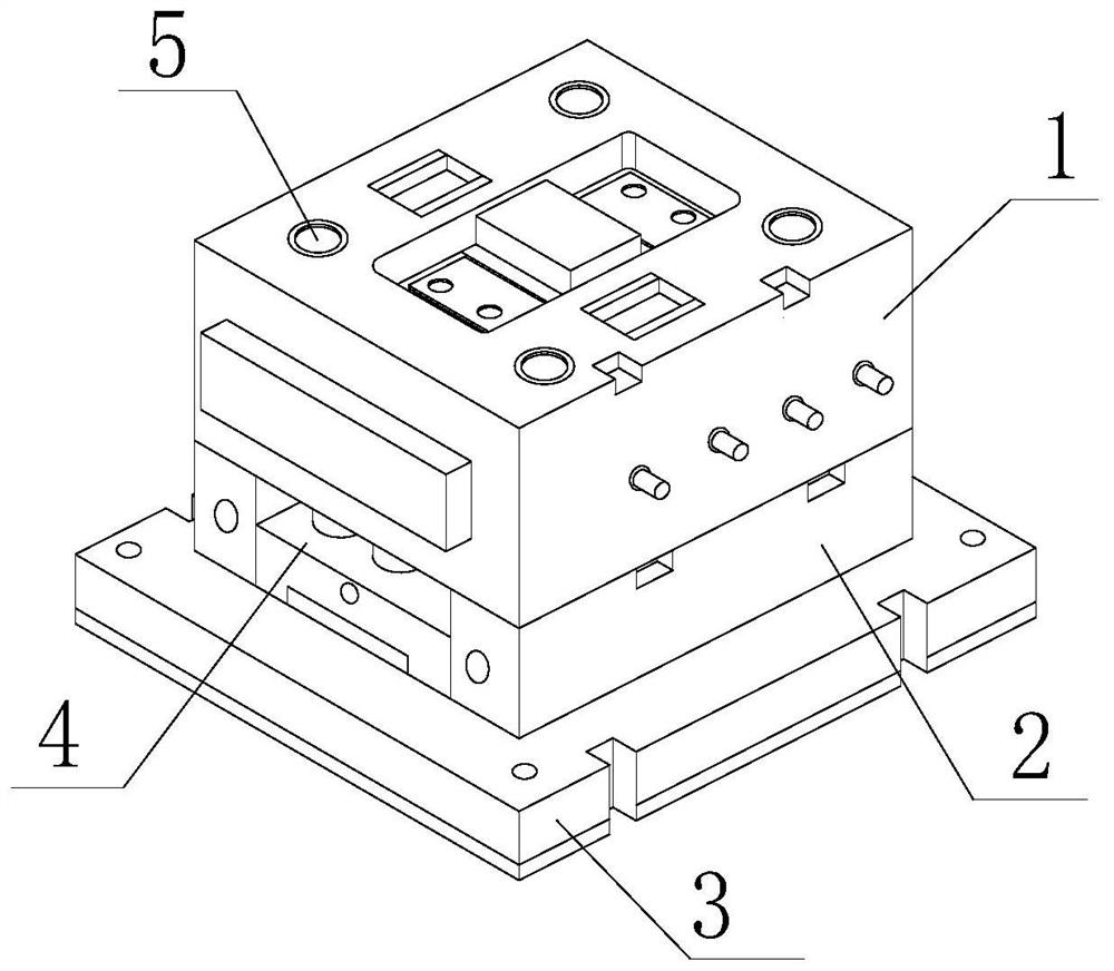
[0035] as Figure 1-10 As shown in the figure, the invention provides a rapid detection mold for finished automotive interior products, including an upper mold 1, a lower mold 2, a fixed base 3, a detection mold 4 and a reinforcing column 5. The interior of the upper mold 1 is provided with a reinforcing column 5, the bottom of the upper mold 1 is provided with a lower mold 2, both sides of the lower mold 2 are provided with connecting grooves, the interior of the connecting groove is arranged at the bottom of the reinforcing column 5, and the bottom of the lower mold 2 is fixedly provided with a fixed base 3, The inner part of the lower die 2 is provided with a detection die 4, the inner part of the detection die 4 is fixedly installed with a die groove, the inner cavity of the die groove is provided with a detection rod 401, both ends of the detection rod 401 are arranged on both sides of the die groove, the inner part of the die groove is provided with a moving groove 402, and t...

Embodiment 2

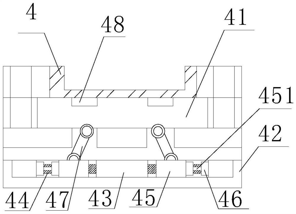
[0038] as Figure 1-10 As shown in the figure, on the basis of embodiment 1, the invention provides a technical scheme: preferably, the ejection mechanism comprises an ejection plate 41, the top of the ejection plate 41 is fixedly equipped with a buffer 48, and the bottom of the ejection plate 41 is provided with an ejection plate 42.

[0039] The inner part of the push out plate 42 is fixedly equipped with a limit block 43, both sides of the limit block 43 are fixedly equipped with a sliding column 44, the outer side of the sliding column 44 is provided with a moving block 45, the side of the moving block 45 is fixedly connected with a telescopic column 451, the other end of the telescopic column 451 is arranged on the inner side of the push out plate 42, the top of the moving block 45 is provided with an ejector rod 47, and the top of the ejector rod 47 is movably installed at the bottom of the ejector plate 41.

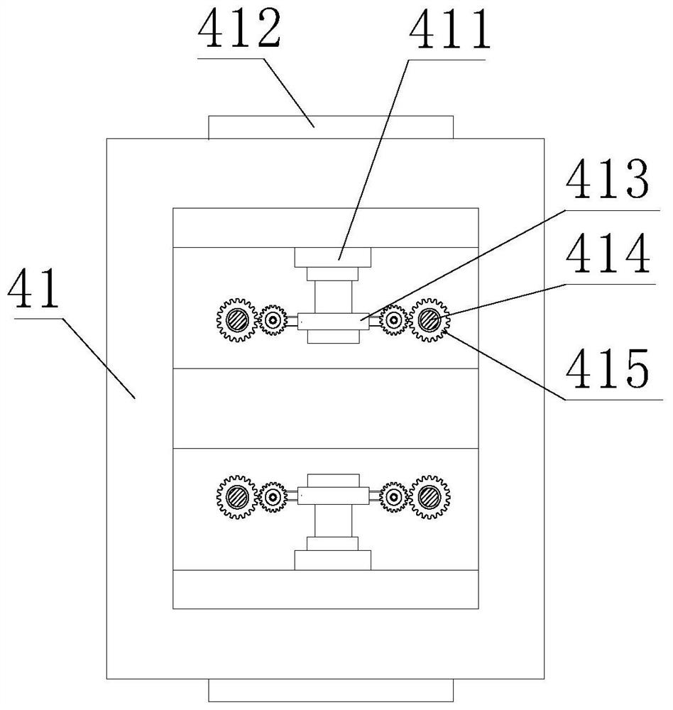
[0040] Both sides of the inner cavity of the ejector plate 41 are ...

Embodiment 3

[0044] as Figure 1-10 As shown in the figure, on the basis of embodiment 1, the invention provides a technical scheme: preferably, a pressing pad 481 is arranged inside the buffer pad 48, an elastic pad 482 is fixedly installed inside the pressing pad 481, an extrusion block 483 is arranged inside the elastic pad 482, a compression column 484 is arranged inside the extrusion block 483, fixed blocks are arranged at both ends of the compression column 484, and extrusion columns 485 are arranged on both sides of the fixed block, The other end of the extrusion column 485 is arranged inside the elastic pad 482.

[0045] In this embodiment, when the cushion 48 is pressed by force, the pressing pad 481 compresses the elastic pad 482 so that the pressing block 483 presses the compression column 484 on the inner side with each other, and then when the fixed block moves down, the pressing column 485 is pushed to squeeze the pressing blocks 483 on both sides, and the rebound force of the press...


PUM


Abstract

The invention discloses an automotive trim finished product rapid detection mold, and relates to the technical field of detection molds, the automotive trim finished product rapid detection mold comprises an upper mold, a lower mold, a fixed base, a detection mold and a reinforcing column, the reinforcing column is arranged in the upper mold, and the lower mold is arranged at the bottom of the upper mold. After the detection of the detection mold is finished, the lifting rod telescopically moves to drive the cleaning block to move into the detection device, so that the scraping block groove abuts against the bottom of the inner cavity of the device, and the scraping block groove is driven to slide at the bottom of the inner cavity of the device in cooperation with the telescopic movement of the detection rod; the detection rod reciprocates, and then the residues in the inner cavity of the device are scraped through the inclination angle of the other side of the scraping block groove, so that the convenient cleaning function is achieved, the problem that the residues need to be manually cleaned due to the fact that the residues adhere to the interior of the mold groove is detected is solved, the cleaning effect of the device is improved, and the detection efficiency is improved. And the function of saving manual labor is achieved.

Description

technical field [0001] The invention relates to the technical field of detection molds, in particular to a rapid detection mold for finished automotive interior products. Background technology [0002] Mold, various molds and tools used in industrial production to obtain required products by injection molding, blow molding, extrusion, die casting or forging molding, smelting, stamping and other methods. In short, mold is a tool used to make molded articles. This tool is composed of various parts, and different molds are composed of different parts. It mainly realizes the processing of object shape through the change of the physical state of the formed material. The existing technology has the following problems: [0003] 1. When the device needs to be disassembled, cleaned or replaced, due to the cumbersome connection, it is difficult to disassemble, resulting in a waste of time, increasing the difficulty of disassembly and reducing the work efficiency; [0004] 2. During the ins...

Claims


Application Information

Patent Timeline
Patent Type & Authority Applications(China)
IPC IPC(8): B29C33/00B29C33/72B29C33/44B29C37/00B29L31/30
CPCB29C33/00B29C33/72B29C33/442B29C37/00B29C2037/90B29L2031/3005
Inventor 姜陈宁
Owner 浙江德清中博机械有限公司
Why Eureka
Try Eureka