Punching forming die of high-density packaged SOT type lead frame and using method thereof

A technology for forming molds and lead frames, which is used in feeding devices, positioning devices, storage devices, etc., can solve the problems of labor-hour consumption, low feeding method efficiency, and time can not meet production needs, etc., to improve the punching speed and simplify the action. effect of timing

Inactive Publication Date: 2019-01-04
TONGLING SANJIA YAMADA TECH
View PDF7 Cites 4 Cited by
  • Summary
  • Abstract
  • Description
  • Claims
  • Application Information

AI Technical Summary

Problems solved by technology

[0004] The technical problem to be solved by the present invention is that the existing high-density SOT product lead frame punching dies can only complete the rib cutting and forming processes, and the separation process needs to be completed with other separation equipment, which consumes extra man-hours At the same time, the die-cutting mold adopts stop nails and claws to cooperate with the lead frame to feed the die into the die-cutting die. A kind of high-density packaging SOT lead frame punching molding die and using method thereof

Method used


Image

  • Punching forming die of high-density packaged SOT type lead frame and using method thereof
  • Punching forming die of high-density packaged SOT type lead frame and using method thereof
  • Punching forming die of high-density packaged SOT type lead frame and using method thereof

Examples


Embodiment 1

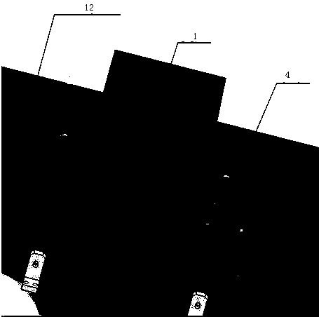
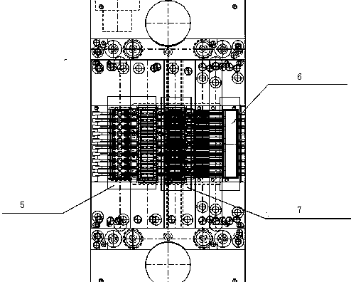
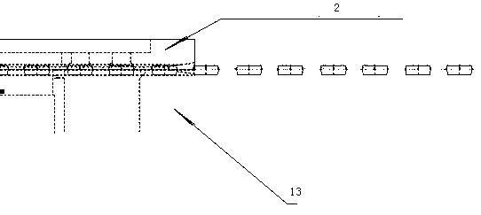
[0019] Embodiment 1: high-density packaging SOT class lead frame punching die, it comprises punching die body 1, is positioned at the feeding cover plate 2 in punching die body, is positioned at punching die body two ends The feeding track 3 and the roller feeding mechanism 4 located at both ends of the punching die body, the punching die body is divided into a punching step 5, a pin forming step 6 and a formed product drop along the lead frame advancing direction. Feeding mouth 7, described roller feeding mechanism comprises the front roller feeding mechanism that is positioned at the front roller feeding mechanism before punching forming mold body and is positioned at the back roller feeding mechanism behind punching forming mold body, and described punching forming mold body includes upper mold and The lower mold, the gap between the feeding cover plate and the lower mold is 0.1mm; the roller feeding mechanism includes a pressure roller 8 that is movably connected to the out...

Embodiment 2

[0020] Embodiment 2: The difference from Embodiment 1 is that the gap between the feeding cover plate and the lower die is 0.15mm, and the rated speed of the motor is 10000r / min.

Embodiment 3

[0021] Embodiment 3: The difference from Embodiment 1 is that the gap between the feeding cover plate and the lower die is 0.2mm, and the rated speed of the motor is 12000r / min.


PUM


Abstract

The invention discloses a punching forming die of high-density packaged SOT type lead frame and a using method of the punching forming die. The punching forming die comprises a punching forming die body (1), a feeding cover plate (2), feeding tracks (3) and roller wheel feeding mechanisms (4), wherein the feeding cover plate (2) is positioned in the punching forming die body, the feeding tracks (3) are positioned at the two ends of the punching forming die body, and the roller wheel feeding mechanisms (4) are positioned at the two ends of the punching forming die body. The punching forming diebody is internally divided into a punching stage (5), a pin forming stage (6) and a formed product blanking port (7) in the advancing direction of the lead frame. The roller wheel feeding mechanism comprises a front roller wheel feeding mechanism and a rear roller wheel feeding mechanism, wherein the front roller wheel feeding mechanism is positioned in front of the punching forming die body, andthe rear roller wheel feeding mechanism is positioned behind the punching forming die body. The punching forming die body comprises an upper die and a lower die, and the gap between the feeding coverplate and the lower die is 0.1-0.2mm. The punching forming die has the beneficial effects that a claw-free die and a high-speed feeding mode are used to realize the movement of the high-density SOT packaging lead frame in the die according to a set step distance.

Description

technical field [0001] The invention relates to the technical field of punching and molding of integrated circuits, in particular to a punching and molding die for a high-density packaging SOT lead frame and a method for using the same. Background technique [0002] With the continuous progress of semiconductor technology, the packaging density of lead frames of SOT products is getting higher and higher, and at the same time, packaging factories have higher and higher requirements for the production capacity of SOT products punching and forming equipment. The action sequence of the traditional SOT lead frame punching and forming equipment needs to match the mold clamping, claw movement, and claw lifting actions at the same time, so the punching speed is only 110 times / min at the highest. The production capacity requirements of SOT lead frame punching and forming equipment generally require 180 times / min. In the existing punching and forming process, the arrangement of the g...

Claims


Application Information

Patent Timeline
Patent Type & Authority Applications(China)
IPC IPC(8): B21D28/02B21D28/14B21D43/08B21D45/04B21F1/00
CPCB21D28/02B21D28/14B21D43/08B21D45/04B21F1/00
Inventor 刘正龙姜开云郑翔徐紫奎王俊
Owner TONGLING SANJIA YAMADA TECH
Why Eureka
Try Eureka