Workpiece clamping device

A technology for tensioning devices and workpieces, applied in chucks and other directions, can solve problems such as low efficiency and laborious alignment of workpieces

Inactive Publication Date: 2019-01-04
郑鑫
View PDF0 Cites 0 Cited by
  • Summary
  • Abstract
  • Description
  • Claims
  • Application Information

AI Technical Summary

Problems solved by technology

[0003] The present invention provides a device for automatic positioning, rapid clamping and unloading to solve the problem of laborious and low efficiency in aligning workpieces in current lathe clamping devices

Method used


Image

  • Workpiece clamping device
  • Workpiece clamping device

Examples


Embodiment Construction

[0010] The present invention will be further described below in conjunction with the accompanying drawings and embodiments.

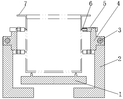
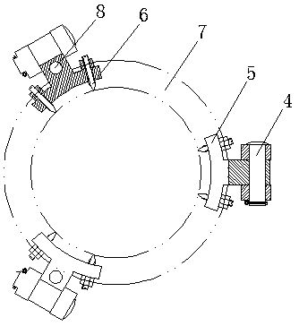
[0011] As shown in the figure, three sets of bases 2 are equidistantly installed on the same circumference of the base plate 1, and the upper end of the base 2 is equipped with a built-in connecting rod 4, and each connecting rod 4 is equipped with two pairs of upper and lower supports 5, Each pair of supports 5 is equipped with two pairs of clamping heads 6; the base 2 and the connecting rod 4 are connected by the surrounding base shaft 3, and the connecting rod 4 and the support 5 are connected by an axial support. The connecting shaft 8 is connected.

[0012] When working, put the barrel-shaped workpiece 7 on the bottom plate 1, the base 2 moves radially inward synchronously under the action of external power, and the base 2 drives the upper connecting rod 4, support 5, and clamping head 6 to the workpiece 7 at the same time. Close, when the clampin...


PUM


Abstract

The invention provides a workpiece clamping device. The workpiece clamping device comprises a bottom plate and bases and is characterized in that the periphery of the bottom plate is equidistantly provided with three sets of the bases in a same circumference, the upper end of each base is provided with a built-in connection rod, each connection rod is provided with upper and lower two pairs of support seats, each support seat is provided with left and right two pairs of clamping heads, the bases are connected with the corresponding connection rods through circumferential base connection shafts, and the connection rods are connected with the corresponding support seats through axial support seat connection shafts. By means of the workpiece clamping device, the problems that present lathe clamping devices are strenuous to align workpieces and low in efficiency are solved, and the workpiece clamping device particularly adapts to assembly and use for clamping cylindrical workpieces in thenumerical control lathe machining process.

Description

technical field [0001] The invention relates to the tooling field of a numerically controlled lathe, in particular to a device for clamping a barrel-shaped workpiece during the machining process of a numerically controlled lathe. Background technique [0002] The current lathe clamping device generally adopts general machine tool fixtures, such as three-jaw, four-jaw chucks, V-shaped block structures, etc. to clamp circular workpieces, and then perform the required processing to achieve the required shape and size. The disadvantage is that it is laborious and inefficient to align the workpiece during use, and the positioning accuracy is also affected by the positioning reference surface of the workpiece. Contents of the invention [0003] The present invention provides a device for automatic positioning, fast clamping and unloading to solve the problems of laborious and low efficiency in aligning workpieces in current lathe clamping devices. [0004] The technical solutio...

Claims


Application Information

Patent Timeline
Patent Type & Authority Applications(China)
IPC IPC(8): B23B31/107
CPCB23B31/107
Inventor 郑鑫
Owner 郑鑫
Why Eureka
Try Eureka