A device and method for removing burrs in workpiece oil passage holes

A technology for oil passage holes and workpieces, which is applied in the field of devices for removing burrs in the oil passage holes of workpieces. It can solve the problems that it is difficult to remove completely where the flushing force is weak, the removal effect is difficult to achieve complete removal, and the diameter of the oil passage hole is small. Achieve the effects of reducing potential safety hazards, simplifying the structure, and increasing the flushing force

Active Publication Date: 2020-05-26
GUANGZHOU YUEYAN INTELLIGENT EQUIP CO LTD
View PDF8 Cites 0 Cited by
  • Summary
  • Abstract
  • Description
  • Claims
  • Application Information

AI Technical Summary

Problems solved by technology

[0005] In the above scheme, the high-pressure water forms a high-pressure water jet through multiple scale-shaped gaps, and the hydraulic pressure is increased for flushing. When passing through a long oil passage hole, the pressure will attenuate, and the flushing force received by different positions in the oil passage hole Not the same, it is difficult to remove the places with weak flushing power
[0006] Therefore, in the prior art, when the diameter of the oil channel hole is small, the length is long, and the internal structure is complicated, such as engine block, cylinder head, etc., its removal effect is difficult to achieve the effect of removal completely. How to provide a cleaning oil The device and method for removing the burr in the oil passage hole of the workpiece with better effect and more thorough removal have become a problem that needs to be solved in the industry

Method used


Image

  • A device and method for removing burrs in workpiece oil passage holes
  • A device and method for removing burrs in workpiece oil passage holes

Examples


Embodiment 1

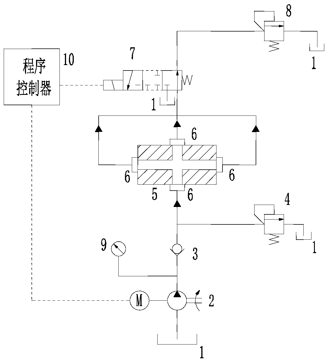
[0038] This embodiment provides a device for removing burrs in the oil passage hole of the workpiece 5, the applicable workpiece 5 includes a plurality of oil passage holes, and the plurality of oil passage holes communicate with each other. Such as figure 1 As shown, the device for removing burrs in the oil passage hole of the workpiece 5 includes: a liquid inlet end and a liquid outlet end.

[0039] The liquid inlet includes a hydraulic pump 2, a one-way valve 3, and a liquid inlet pipe (not shown in the figure), one end of the liquid inlet pipe is connected to the one-way valve 3, and the other end of the liquid inlet pipe is connected to at least one oil passage hole of the workpiece 5 ; The hydraulic pump 2 pumps liquid from the mailbox 1 and enters the oil passage hole in the workpiece 5 through the check valve 3, and flows to the liquid outlet. The liquid passes through the hydraulic pump 2 to the check valve 3, and a pressure gauge 9 is set to monitor the pressure of ...


PUM


Abstract

The invention provides a device for removing burrs in workpiece oil channel holes. The device comprises a liquid inlet end and a liquid outlet end. The liquid inlet end comprises a hydraulic pump, a check valve and a liquid inlet pipe. One end of the liquid inlet pipe communicates with the check valve. The other end of the liquid inlet pipe communicates with at least one oil channel hole of a workpiece. The liquid outlet end comprises a liquid outlet pipe, a reversing valve and a back pressure valve. One end of the liquid outlet pipe communicates with at least one oil channel hole of the workpiece. The other end of the liquid outlet pipe communicates with the reversing valve. The other end of the reversing valve communicates with the back pressure valve. The invention further provides a corresponding method for removing the burrs. Through two times of hydraulic shocks, liquid forms hydraulic vibration shock waves in the oil channel holes, thus the insides of the oil channel holes are washed repeatedly at high pressure, the burrs in the oil channel holes are removed completely, and the conditions that in the workpiece use process, burrs fall off to damage other devices and the wholeequipment are avoided effectively.

Description

technical field [0001] The invention relates to a device and a method for removing burrs in oil passage holes of workpieces. Background technique [0002] At present, in the technical field of removing and cleaning the burrs in the oil passage hole of the workpiece, brushes with different hardness are mainly used to move back and forth to remove them, and then perform high-pressure flushing by hydraulic pressure. Because some workpieces, such as automobile engine block and cylinder head, have small diameter and long length of oil passage holes, the burrs in the oil passage holes, especially the burrs at the intersection of two oil passage holes, are difficult to remove with a brush, Generally, it is difficult for high-pressure liquid to completely wash the burrs in the oil passage hole. These burrs have not been completely removed. Once they fall off due to vibration, collision or pressure shock during engine use and then run with the oil, serious quality problems such as s...

Claims


Application Information

Patent Timeline
Patent Type & Authority Patents(China)
IPC IPC(8): B23D79/00
CPCB23D79/00
Inventor 陈卫华陈恬生
Owner GUANGZHOU YUEYAN INTELLIGENT EQUIP CO LTD
Why Eureka
Try Eureka