A device for mixing and discharging concrete pouring parts

A technology of discharging device and pouring piece, which is applied to cement mixing device, unloading device, clay preparation device and other directions, can solve the problems of large size of the device, slow pouring of pouring parts, inability to pour, etc., and achieves compact structure design and operation efficiency. High, smooth discharge effect

Active Publication Date: 2020-12-29
天长市大成建筑有限公司
View PDF8 Cites 0 Cited by
  • Summary
  • Abstract
  • Description
  • Claims
  • Application Information

AI Technical Summary

Problems solved by technology

Concrete mixing is divided into two types: manual mixing and mechanical mixing of water. Concrete mixing plants are widely used in my country's industry, agriculture, transportation, national defense, water conservancy, municipal and other construction projects, and the demand is increasing. At present, independent concrete pouring parts However, due to the imperfect and unreasonable design of the currently used concrete pouring and mixing discharge device, various problems occur in actual production and use, which seriously restricts its application and development.
[0003] In order to solve the above problems, the present invention is proposed, which overcomes the currently used concrete pouring mixing and discharging device. Due to the direct mixing structure and the different sizes of the raw materials, the feeding channel is easy to be stuck during pouring, resulting in slow pouring of the pouring parts. Even problems such as pouring cannot be solved, which solves the problems of the currently used concrete pouring mixing and discharging device. Due to the multi-power drive structure, the device is too large and the transmission efficiency of the device is low. , smooth discharge, smooth pouring, high operating efficiency, etc.

Method used


Image

  • A device for mixing and discharging concrete pouring parts
  • A device for mixing and discharging concrete pouring parts
  • A device for mixing and discharging concrete pouring parts

Examples


Embodiment Construction

[0015] The following will clearly and completely describe the technical solutions in the embodiments of the present invention with reference to the accompanying drawings in the embodiments of the present invention. Obviously, the described embodiments are only some, not all, embodiments of the present invention. Based on the embodiments of the present invention, all other embodiments obtained by persons of ordinary skill in the art without making creative efforts belong to the protection scope of the present invention.

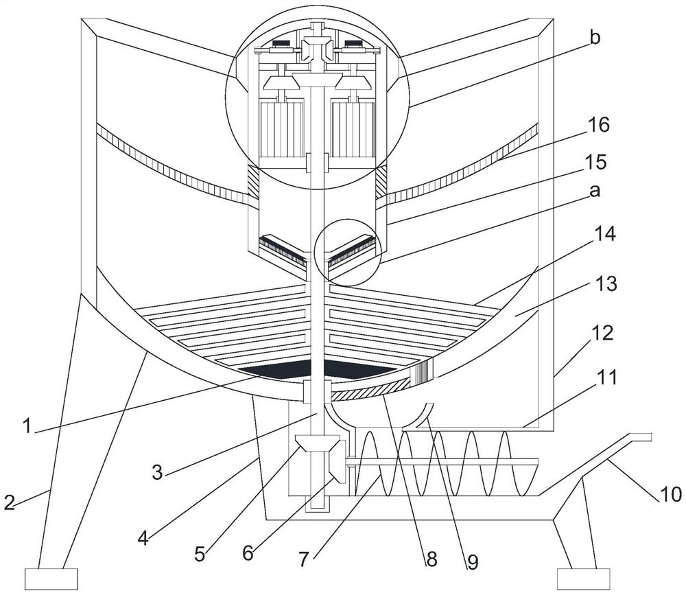
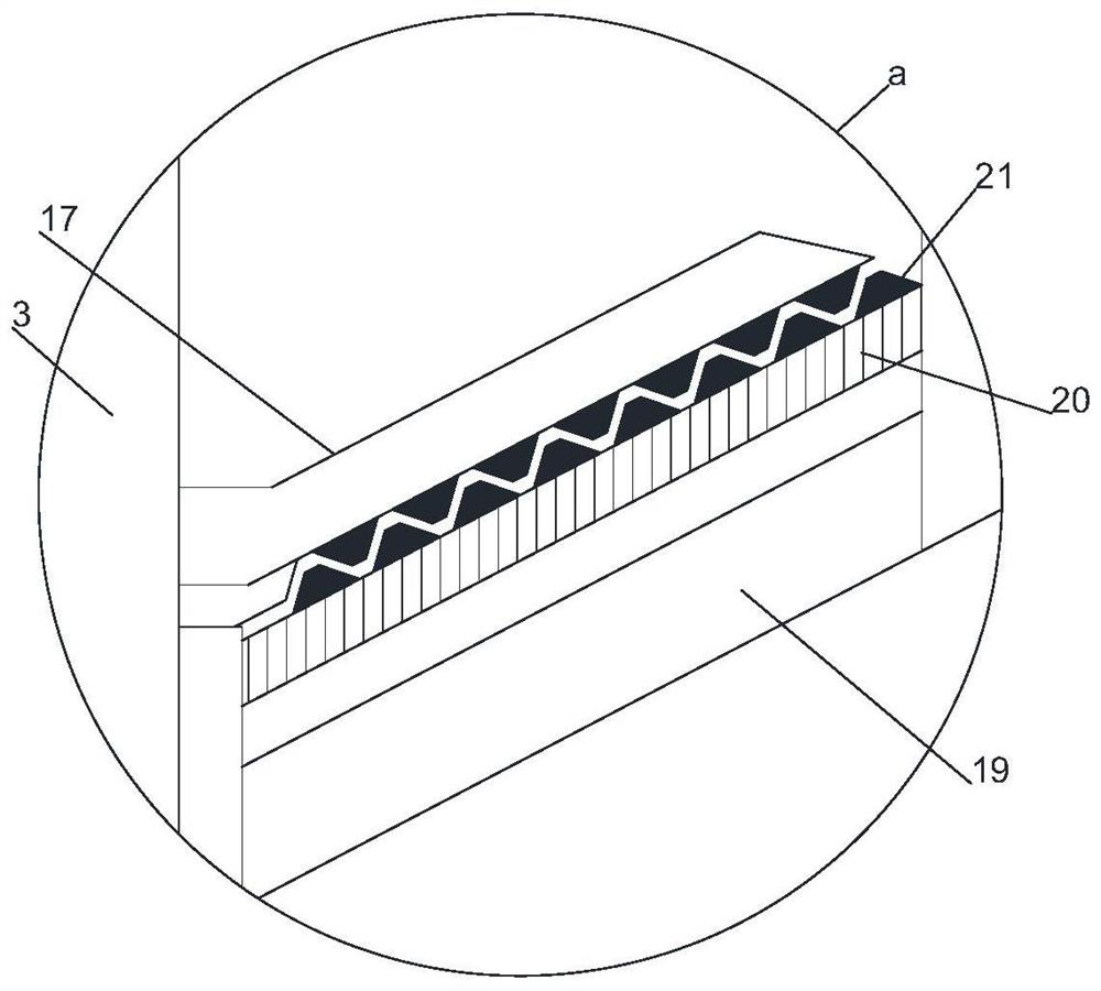
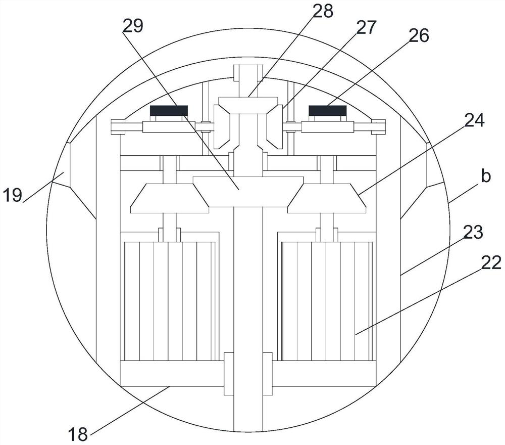
[0016] see Figure 1~4 , in an embodiment of the present invention, a mixing and discharging device for concrete pouring parts, including a vertically arranged operation installation cylinder 12, a transmission crushing installation cylinder 15 is arranged vertically downward at the middle position of the upper end of the operation installation cylinder 12, and the transmission The lower half of the crushing installation cylinder 15 cooperates with the operati...


PUM


Abstract

The invention discloses a concrete pouring piece stirring and discharging device which comprises a vertically-arranged operation installing cylinder. A transmission breaking installing cylinder is arranged at the middle of the upper end of the operation installing cylinder in a vertically-downward mode, the lower half section of the transmission breaking installing cylinder is externally matched with the operation installing cylinder to be provided with an annular arc bottom guiding screen, a plurality of feeding inlets are formed in the lower end of the annular arc bottom guiding screen matched with the transmission breaking installing cylinder at equal angles, a main driving shaft runs through the middle of the upper half section of the transmission breaking installing cylinder through ahorizontally-arranged fixed installing plate, synchronous driving motors are symmetrically embedded at the portions, on the left and right sides of the main driving motor, of the fixed installing plate through a vertically-arranged motor installing cylinder, and a transmission partition plate is horizontally arranged inside the portion, above the synchronous driving motors, of the transmission breaking installing cylinder. The device has the advantages of being compact in structural design, achieving stirring pre-screening and breaking, smooth in discharging, smooth in pouring, high in operation efficiency and the like.

Description

technical field [0001] The invention relates to the field of construction machinery, in particular to a stirring and discharging device for poured concrete parts. Background technique [0002] Concrete mixing is an operation method in which cement, lime, water and other materials are mixed and then stirred evenly. Concrete mixing is divided into two types: manual mixing and mechanical mixing of water. Concrete mixing plants are widely used in my country's industry, agriculture, transportation, national defense, water conservancy, municipal and other construction projects, and the demand is increasing. At present, independent concrete pouring parts However, due to the imperfect and unreasonable design of the currently used concrete pouring mixing and discharging device, various problems occur in actual production and use, which seriously restricts its application and development. [0003] In order to solve the above problems, the present invention is proposed, which overcomes...

Claims


Application Information

Patent Timeline
Patent Type & Authority Patents(China)
IPC IPC(8): B28C5/16B28C5/08B28C7/00B28C7/16B02C13/14
CPCB02C13/14B28C5/0818B28C5/0831B28C5/0887B28C5/16B28C7/0007B28C7/167
Inventor 孙江花
Owner 天长市大成建筑有限公司
Why Eureka
Try Eureka