Eureka AIR delivers breakthrough ideas for toughest innovation challenges, trusted by R&D personnel around the world.

Plate feeding device

A panel and roof technology, which is applied in the field of panel production equipment, can solve problems affecting work efficiency and inflexible operation, and achieve the effects of improving work efficiency, flexible start and stop, and convenient transportation

Inactive Publication Date: 2019-01-04
嘉善缔嘉装饰材料有限公司
View PDF5 Cites 0 Cited by
  • Summary
  • Abstract
  • Description
  • Claims
  • Application Information

AI Technical Summary

Problems solved by technology

The existing panel loading device is inflexible in operation and only has the function of transporting the material box. It requires manual or other equipment to transfer the material box to the loading and unloading machine, which affects the improvement of work efficiency.

Method used


Image

  • Plate feeding device
  • Plate feeding device
  • Plate feeding device

Examples


Embodiment Construction

[0018] In order to make the technical means, creative features, goals and effects achieved by the present invention easy to understand, the present invention will be further elaborated below in conjunction with illustrations and specific embodiments.

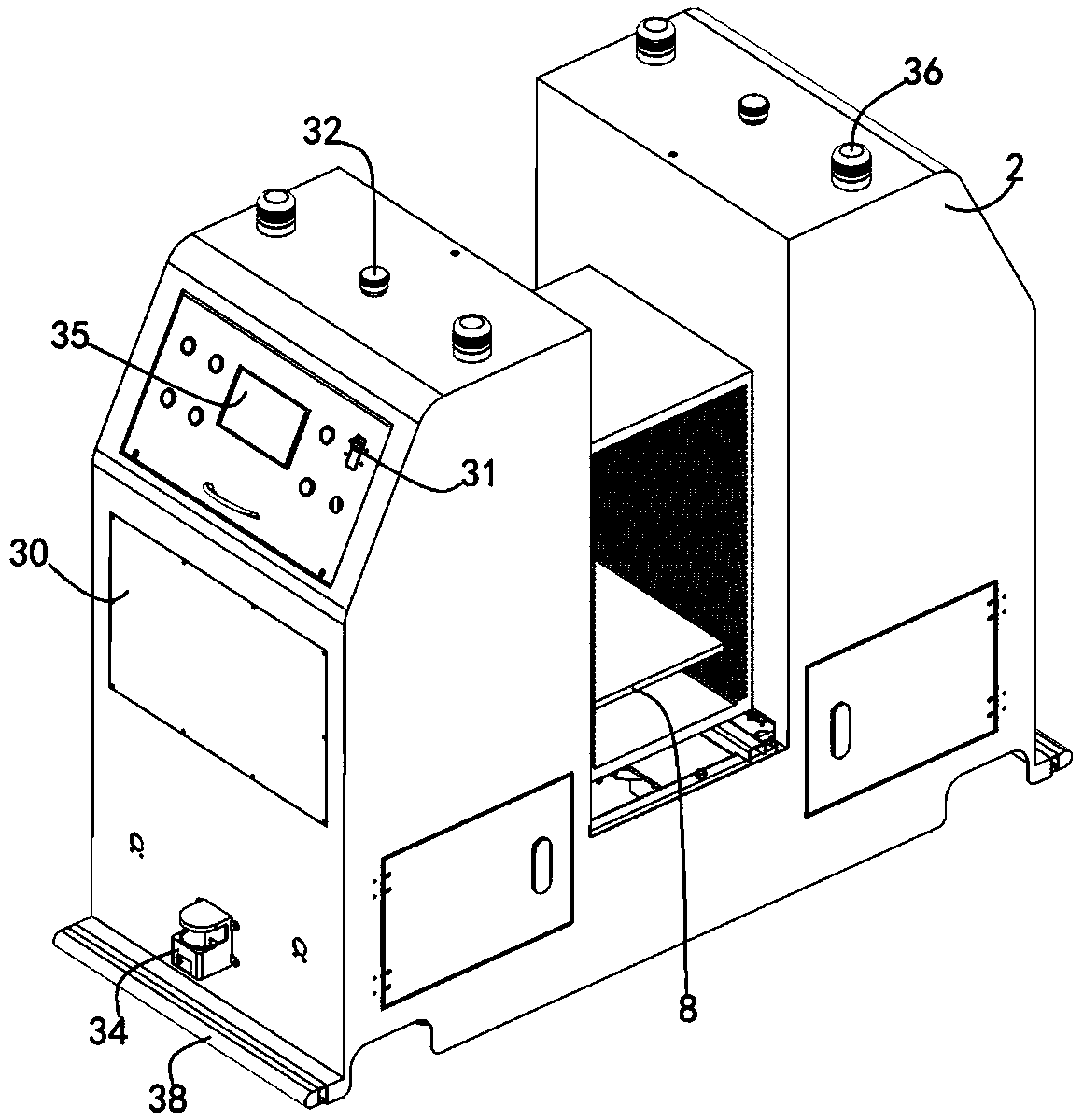
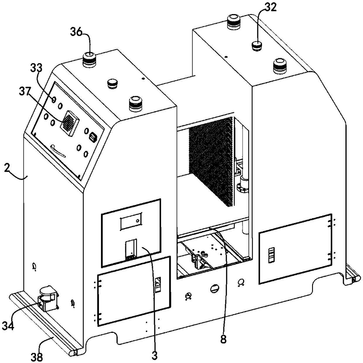
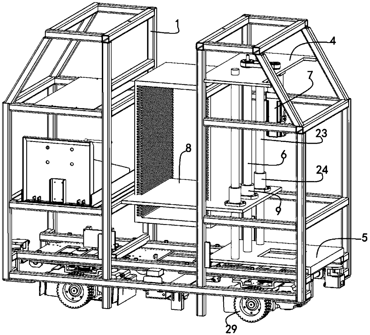
[0019] like Figure 1 ~ Figure 4 As shown, the plate feeding device proposed by the present invention includes a frame body, a drive mechanism is provided at the bottom of the frame body, and a lifting mechanism is provided in the frame body, and the frame body and the lifting mechanism are driven by the drive mechanism to move. Covered with a shell plate 2, a set of universal wheels is provided at the bottom of the frame, and a battery box 3 is provided on the frame, and the battery box is electrically connected with the driving mechanism and the lifting mechanism; the lifting mechanism includes a top plate 4 and a bottom plate 5, and the top plate and the bottom plate are fixed on the frame Among them, a lead screw 6 is provid...


PUM


Abstract

The invention provides a plate feeding device. The plate feeding device comprises a frame body, a driving mechanism is disposed at the bottom of the frame body, and a lifting mechanism is arranged inthe frame body. The lifting mechanism comprises a top plate and a bottom plate, and lead screws are arranged between the top plate and the bottom plate. The top plate is provided with a lifting motor,and the lead screws are provided with a lifting platform. The lifting platform is internally provided with lifting nuts, and the lead screws penetrate through the lifting nuts. The driving mechanismcomprises a mounting assembly, a driving assembly and an adjusting assembly, the mounting assembly comprises a mounting plate, and the driving assembly and the adjustment assembly are mounted and arranged on the mounting plate. The driving assembly is internally provided with a lifting plate, a fixed wing piece is arranged at one end of the lifting plate, a movable wing piece is arranged at the other end of the lifting plate, and a rotating rod is arranged at the tail end of the fixed wing piece. The adjusting assembly includes a hoist motor, and a rotating shaft is arranged at the tail end ofa power shaft of the hoist motor. A cam bearing is arranged at the edge of the rotating shaft, and a pry bar is arranged on the outer side of the hoist motor. A supporting piece is arranged at one end of the pry bar, and a jacking piece is arranged at the other end of the pry bar. The supporting piece is located under the cam bearing, and the jacking piece is located under the movable wing pieceof the lifting plate.

Description

technical field [0001] The invention relates to plate production equipment, in particular to a plate feeding device. Background technique [0002] Plate loading and unloading devices play an important role in the process of plate production and storage. They are usually powered by batteries and equipped with non-contact guiding devices. With the help of computer control and guiding devices, they can accurately reach the destination . The existing panel loading device is inflexible in operation and only has the function of transporting the material box. It requires manual or other equipment to transfer the material box to the loading and unloading machine, which affects the improvement of work efficiency. Therefore, it is necessary to optimize the structure of this plate feeding device to overcome the above-mentioned defects. Contents of the invention [0003] The purpose of the present invention is to provide a plate feeding device to improve the turnover efficiency of t...

Claims


Application Information

Patent Timeline
IPC IPC(8): B65G47/74
CPCB65G47/74
Inventor 陈清明
Owner 嘉善缔嘉装饰材料有限公司
Why Eureka
Eureka Blog
Learn More