Steel mold trolley for tunnel side wall concrete lining

A steel mold trolley and concrete technology, which is applied in tunnel lining, shaft lining, tunnel, etc., can solve the problems of large steel mold trolley, increased construction cost, poor adaptability, etc., and achieves simple design structure and convenient installation and disassembly , quality controllable effect

Pending Publication Date: 2019-01-04
CHINA INTERNATIONAL WATER & ELECTRIC CORPORATION +2
View PDF7 Cites 1 Cited by
  • Summary
  • Abstract
  • Description
  • Claims
  • Application Information

AI Technical Summary

Problems solved by technology

However, the prominent disadvantages of the full-section steel formwork trolley lining in the prior art are: the steel formwork trolley is bulky and heavy, and it is inconvenient to install, move, and dismantle; the cost of manufacturing and installation is high, and it is difficult to amortize the cost of a short tunnel. The larger the section and the higher the side wall, the higher the amortization cost; the adaptability is relatively poor, and it is difficult for the steel formwork trolley to turn in the cave, and it is impossible to realize the small curvature turning; the construction process cannot be monitored intuitively, and it cannot be timely When construction defects are found, the concrete cannot be maintained in time, and the mold can only be demoulded after it is strengthened, and the concrete construction defects cannot be effectively treated and maintained in time; the versatility is not good, and it is suitable for the bending section, gradient section and side wall height change parts of the tunnel If it cannot be used, other methods of lining are required, which will affect the construction speed and increase the construction cost

Method used


Image

  • Steel mold trolley for tunnel side wall concrete lining
  • Steel mold trolley for tunnel side wall concrete lining
  • Steel mold trolley for tunnel side wall concrete lining

Examples


Embodiment 1

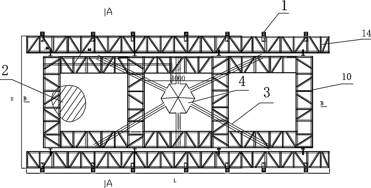
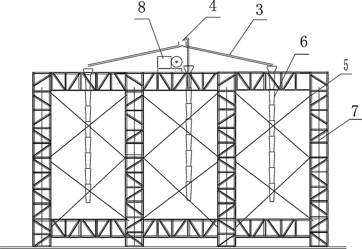
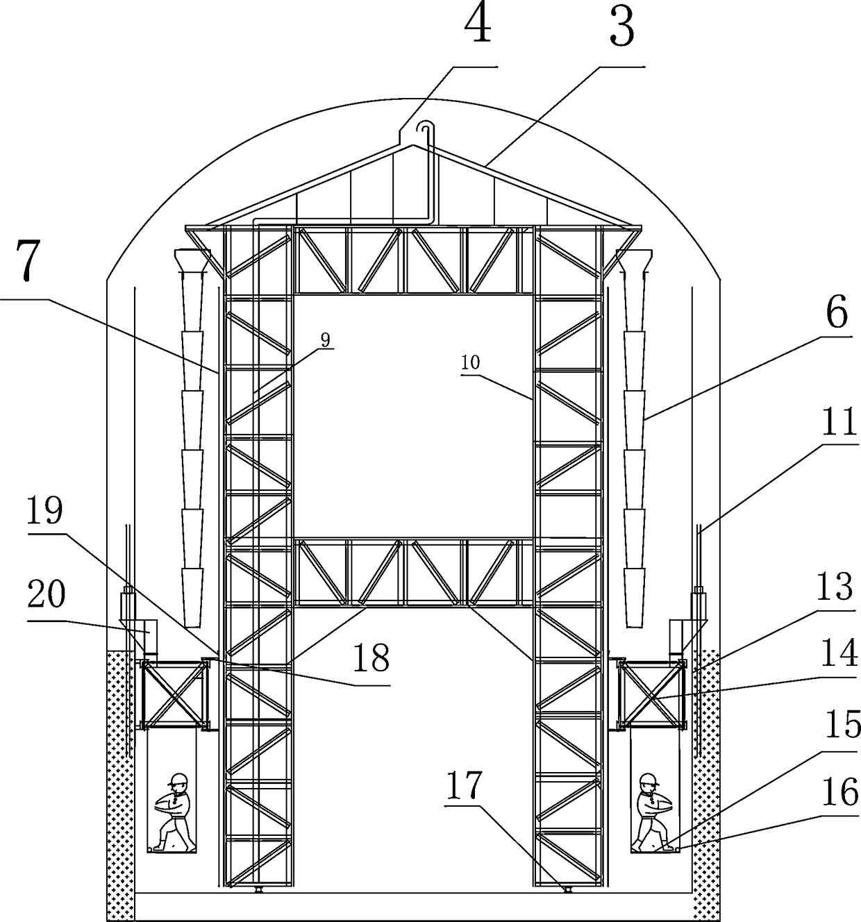
[0022] Such as Figure 1~5 Among them, a steel mold trolley for the concrete lining of the tunnel side wall, including a trolley 10, trusses 14 are arranged on both sides of the trolley 10, slide rails 7 are arranged on both sides of the trolley 10, and the truss 14 is installed on the slide The slider 19 on the rail 7 is connected, and the template 13 is fixedly connected to one end of the truss 14. A lifting mechanism is provided on the trolley 10, and the lifting mechanism drives the truss 14 to move up and down. With this structure, the lining of the tunnel side wall and the high wall of the tunnel can be realized. The difficult-to-lining areas are resolved, and the lifting system also ends up synovial well.

[0023] In the preferred solution, the lifting mechanism is a compression rod mechanism, including a support rod 11 and a jack 1, the support rod 11 is buried in the concrete, the truss 14 is provided with a lifting frame 20, the lifting frame 20 is installed on the j...

Embodiment 2

[0032] Manufacture of formwork 13: Manufacture in sections according to the design requirements in the manufacturing workshop, check and accept after pre-assembly, and number the sections after passing the test.

[0033] Reinforcement installation: It can be installed in advance, or it can be installed and slipped along with the slipform construction; it is recommended to install the reinforcement first to facilitate the rapid construction of concrete.


PUM


Abstract

The invention provides a steel mold trolley for tunnel side wall concrete lining, thereby realizing quick lining of the full section of the tunnel concrete. Lifting frames are arranged at the two sides of the trolley and are connected to the two sides of the trolley by sliding rails and sliding blocks. Templates and jacks are arranged on the lifting frames. The templates need segmented manufacturing and installation; and the jacks serving as power sources of the lifting frames are used for lifting the lifting frames gradually to realize a sliding membrane effect. The steel mold trolley that isused for quick construction of the tunnel side wall concrete has advantages of simple structure, great convenience in mounting and dismounting, low cost, and high adaptability and is capable of monitoring the construction process at any time and carrying out maintenance and construction quality defect repairing timely.

Description

technical field [0001] The patented technology of the invention relates to the construction method of the concrete lining of the tunnel, in particular to a sliding formwork for the concrete lining of the side wall of the tunnel. Background technique [0002] At present, the concrete lining of the tunnel side wall usually uses a steel formwork trolley, which can realize the rapid lining of the entire tunnel concrete section. However, the prominent disadvantages of the full-section steel formwork trolley lining in the prior art are: the steel formwork trolley is bulky and heavy, and it is inconvenient to install, move, and dismantle; the cost of manufacturing and installation is high, and it is difficult to amortize the cost of a short tunnel. The larger the section and the higher the side wall, the higher the amortization cost; the adaptability is relatively poor, and it is difficult for the steel formwork trolley to turn in the hole, and it is impossible to realize the small...

Claims


Application Information

Patent Timeline
Patent Type & Authority Applications(China)
IPC IPC(8): E21D11/10
CPCE21D11/102
Inventor 陈育权王涛吴世然任强侯彬李进军宋求明熊德政王江杜思存朱小春章琦云李学凯赵博刘永年孙旭生胡清林
Owner CHINA INTERNATIONAL WATER & ELECTRIC CORPORATION
Why Eureka
Try Eureka