A heat tracing pipeline efficiency-enhancing installation device

A technology for installing device and heat tracing pipe, which is applied in the direction of pipe heating/cooling, pipe/pipe joint/pipe fitting, mechanical equipment, etc., which can solve the problem of unsatisfactory heat tracing effect, compression of the space around the main pipe, and difficulty in fixing long-distance heat tracing pipes, etc. problems, to reduce workload, improve installation efficiency, and avoid classification work.

Active Publication Date: 2020-08-18
XIAN TPRI BOILER ENVIRONMENTAL PROTECTION ENG CO LTD
View PDF6 Cites 0 Cited by
  • Summary
  • Abstract
  • Description
  • Claims
  • Application Information

AI Technical Summary

Problems solved by technology

In the past installation process of heat tracing pipelines, more attention was paid to the supervision of the distance between the heat tracing pipe and the main pipe, while the relative position fixing between the heat tracing pipes and the establishment of the "cavity" of the air layer around the main pipe were ignored, resulting in the final heat tracing Unsatisfactory effect
At this time, people often increase the hot water, steam flow or increase the temperature to strengthen the heat tracing, although it can solve the problem, but reduces the thermal efficiency of the heat tracing system
The reason is that it is difficult to fix the long-distance heating pipe during the installation of the heating pipe, and the external insulation layer needs to be fastened, which greatly compresses the space around the main pipe.

Method used


Image

  • A heat tracing pipeline efficiency-enhancing installation device
  • A heat tracing pipeline efficiency-enhancing installation device
  • A heat tracing pipeline efficiency-enhancing installation device

Examples


Embodiment Construction

[0022] The present invention is described in further detail below in conjunction with accompanying drawing:

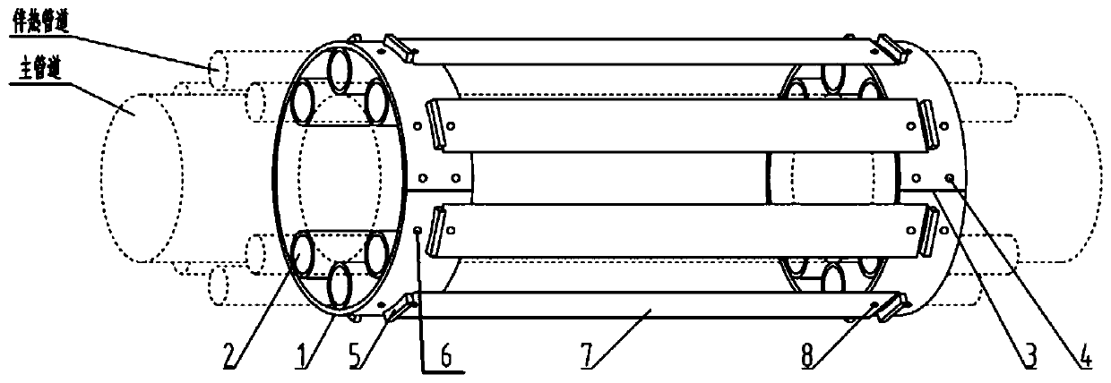
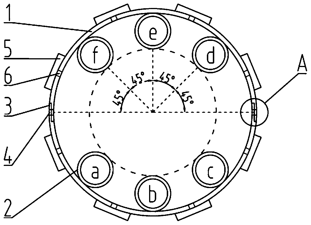
[0023] refer to Figure 1 to Figure 3 , the heat tracing pipe efficiency installation device according to the present invention includes a thermal insulation layer and a number of annular locators 1 distributed sequentially along the main pipe, wherein each annular locator 1 is socketed on the main pipe, and the inner wall of each annular locator 1 There is a heat tracing tube positioning cylinder 2 for the passage of the heat tracing pipe on the top, and a number of inner braces 7 are connected between two adjacent annular positioners 1, and all inner braces between two adjacent annular positioners 1 The plates 7 are distributed along the circumferential direction, and each annular positioner 1 and each inner support plate 7 are wrapped in the insulation layer, and a cavity structure is formed between the insulation layer and the main pipeline. Generally, there are e...


PUM


Abstract

The invention discloses a heat tracing pipeline synergy installation device. The heat tracing pipeline synergy installation device comprises an insulation layer and a plurality of annular locators arranged in sequence along a main pipeline, each annular locator is connected to the main pipeline in a sleeving mode, and the inner wall of each annular locator is provided with a heat tracing pipelinepositioning cylinder for a heat tracing pipe to pass through, every two adjacent annular locators are connected by a plurality of inner supporting plates, and the inner supporting plates between everytwo adjacent annular locators are distributed circumferentially. Each annular locator and each inner supporting plate are wrapped with the insulation layer, and a cavity structure is formed between the insulation layer and the main pipeline. The heat tracing pipeline synergy installation device can effectively improve the heat tracing effect and operation efficiency of a heat tracing pipe.

Description

technical field [0001] The invention belongs to the technical field of energy saving of hot water or steam heat tracing systems, and relates to a heat tracing pipeline efficiency-enhancing installation device. Background technique [0002] Pipeline conveying systems widely exist in various production lines in the industrial field and become the most important part of various process production lines. With the development of industrial technology and the emergence of more special media, the pipeline transportation system puts forward stricter control requirements for the operating temperature of the pipeline. In order to ensure the safety and stability of pipeline transportation, the method of temperature compensation along the main pipeline has become the main solution for the temperature control of pipeline operation. The main advantage of pipeline heat tracing is that it is independent from the main system and can be adjusted arbitrarily according to the path of the main ...

Claims


Application Information

Patent Timeline
Patent Type & Authority Patents(China)
IPC IPC(8): F16L53/32
CPCF16L53/32
Inventor 李明皓李刚许博秦昶顺贾晓静
Owner XIAN TPRI BOILER ENVIRONMENTAL PROTECTION ENG CO LTD
Why Eureka
Try Eureka