
Refrigerator box connecting structure

A technology for connecting structures and cabinets, applied in lighting and heating equipment, household appliances, household refrigeration devices, etc., can solve problems such as difficult loading and unloading, refrigerator cabinets cannot be connected with complex refrigerators, and achieve the effect of simple operation

Pending Publication Date: 2019-01-04
CHANGHONG MEILING CO LTD
View PDF0 Cites 0 Cited by
  • Summary
  • Abstract
  • Description
  • Claims
  • Application Information

AI Technical Summary

Problems solved by technology

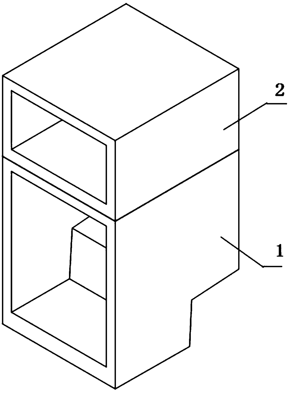
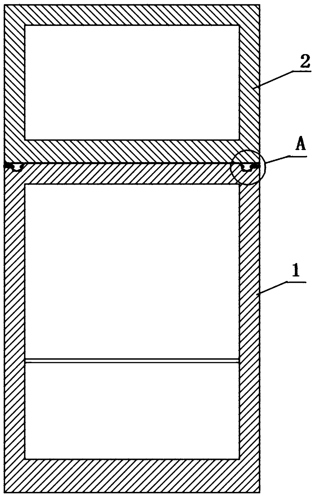
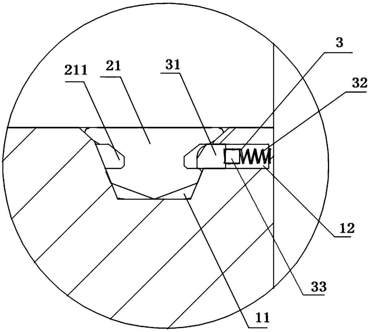
[0005] The purpose of the present invention is to provide a connection structure for refrigerator cabinets, through which the fixed adjustment feet at the bottom of the upper cabinet are matched with the round table holes opened at the corresponding positions on the top of the lower cabinet; The rectangular block of the magnetic buckle block matches the annular groove to realize the tight locking of the upper box and the lower box; when disassembling, place a magnet to absorb the iron block at the corresponding position of the chute hole on the side of the lower box and then drive the rectangular block Move into the chute hole to realize unlocking, which solves the problem that the existing refrigerator box cannot be freely combined through the connection structure or the refrigerator connection structure is complex and difficult to assemble and disassemble

Method used


Image

  • Refrigerator box connecting structure
  • Refrigerator box connecting structure
  • Refrigerator box connecting structure

Examples


Embodiment Construction

[0019] The following will clearly and completely describe the technical solutions in the embodiments of the present invention with reference to the accompanying drawings in the embodiments of the present invention. Obviously, the described embodiments are only some, not all, embodiments of the present invention. Based on the embodiments of the present invention, all other embodiments obtained by persons of ordinary skill in the art without creative efforts fall within the protection scope of the present invention.

[0020] In the description of the present invention, it should be understood that the terms "upper", "lower", "top", "inner" and the like indicate orientation or positional relationship, and are only for the convenience of describing the present invention and simplifying the description, rather than indicating or It should not be construed as limiting the invention by implying that a referenced component or element must have a particular orientation, be constructed a...


PUM


Abstract

The invention discloses a refrigerator box connecting structure and relates to the technical field of refrigerator box connection structures. The refrigerator box connecting structure comprises a lower box body and an upper box body, wherein adjusting feet of the circular truncated cone structure are fixed at the four corners of the bottom part of the upper box body; an annular groove is formed inthe side around each adjusting foot; circular truncated cone holes are formed in positions of the four corners of the bottom part of the lower box body corresponding to the adjusting feet; the lowerpart of each adjusting foot is a narrow end and is matched with the circular truncated cone hole; a sliding slot hole is formed in the side of each circular truncated cone hole; a magnetic buckle stopblock is installed in each sliding slot hole; each magnetic buckle stop block comprises a rectangular stop block; the side of each rectangular stop block is fixedly provided with springs and an ironblock. The invention realizes the locking of the upper box body and the lower box body by matching the rectangular stop blocks of the magnetic buckle stop blocks with the annular grooves; when disassembling, magnet adsorption iron blocks are placed at the corresponding positions of the sliding slot holes in the side faces of the lower box body to drive the rectangular stop blocks to move into thesliding slot holes to realize unlocking, which is convenient and quick; at the same time, the connection structure is completely located inside the box body, thereby avoiding the danger caused by theconnection structure protruding the refrigerator box.

Description

technical field [0001] The invention belongs to the technical field of refrigerator box connection structures, and in particular relates to a refrigerator box connection structure. Background technique [0002] Refrigerators currently on the market are specific products with fixed sizes and functions, which cannot meet the requirements of free customization according to the actual needs of users and space requirements. [0003] The existing box connection schemes all need to add redundant parts and use screws to connect the box. On the one hand, the parts protrude from the surface of the refrigerator, and the protruding parts pose safety hazards during use. On the other hand, the existing connection structure is complicated. , It is inconvenient to disassemble and assemble, and it is inconvenient to use. [0004] The present invention is devoted to research and development of a refrigerator cabinet connection structure, which is used to solve the problems that the existing ...

Claims


Application Information

Patent Timeline
IPC IPC(8): F25D23/06
CPCF25D23/065
Inventor 田亚明魏邦福李乾坤
Owner CHANGHONG MEILING CO LTD
Learn More