
Six-component test stand and method for measuring vector thrust

A technology of six-component force and test bench, which is applied to force/torque/power measuring instruments, measuring devices, jet engine testing, etc., which can solve the problems of measurement error, small amount of information harvested, and labor-intensive, etc., to improve bearing capacity Ability, easy installation, simple structure effect

Pending Publication Date: 2019-01-04
BEIJING AEROSPACE SANFA HIGH TECH
View PDF4 Cites 16 Cited by
  • Summary
  • Abstract
  • Description
  • Claims
  • Application Information

AI Technical Summary

Problems solved by technology

The main reason is that the flight test is costly, long cycle, small amount of information harvested, risky, and requires a lot of manpower
This requires the ground test of the engine. The ground test of the engine refers to the static test of the system on the ground according to specific conditions and environmental requirements, and obtains information describing various performance indicators of the system, so as to solve the problems in the process of engine thrust eccentricity test. The key problem, however, in the prior art, there is no mature technology for the experimental equipment of the engine vector force, especially the experimental equipment of the six-component force vector force of the engine. At the same time, the six-component force vector thrust measurement technology in the prior art, especially It is a horizontal six-component force vector thrust measurement technology, which does not consider the gravity of the engine or there is no good way to consider the influence of the gravity of the engine, resulting in large errors in the measurement results

Method used


Image

  • Six-component test stand and method for measuring vector thrust
  • Six-component test stand and method for measuring vector thrust
  • Six-component test stand and method for measuring vector thrust

Examples


Embodiment Construction

[0054] In describing the present invention, it should be understood that the terms "center", "longitudinal", "transverse", "length", "width", "thickness", "upper", "lower", "front", " Back", "Left", "Right", "Vertical", "Horizontal", "Top", "Bottom", "Inner", "Outer", "Clockwise", "Counterclockwise", "Axial", The orientation or positional relationship indicated by "radial", "circumferential", etc. is based on the orientation or positional relationship shown in the drawings, and is only for the convenience of describing the present invention and simplifying the description, rather than indicating or implying the referred device or element Must be in a particular orientation, be constructed in a particular orientation, and operate in a particular orientation, and therefore should not be construed as limiting the invention. In addition, the features defined as "first" and "second" may explicitly or implicitly include one or more of these features. In the description of the prese...


PUM


Abstract

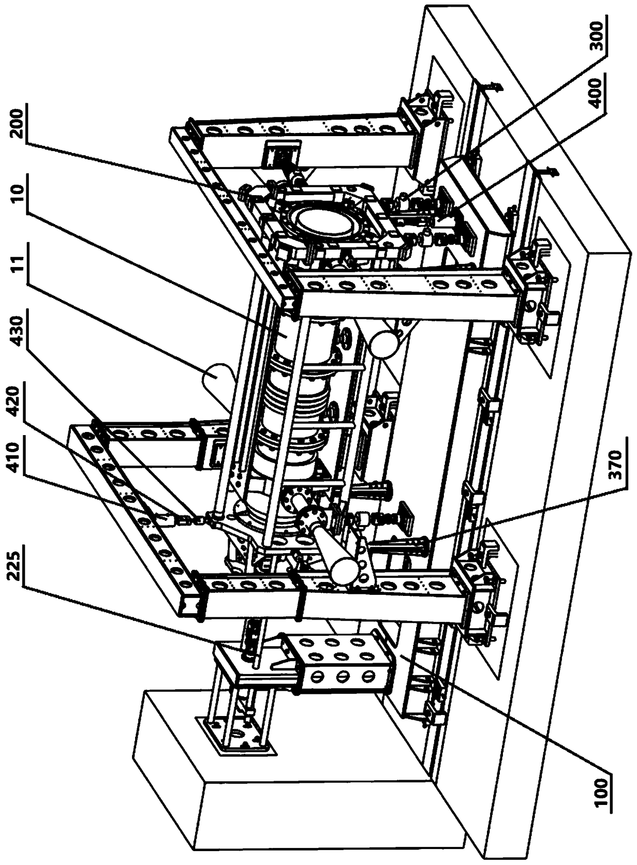
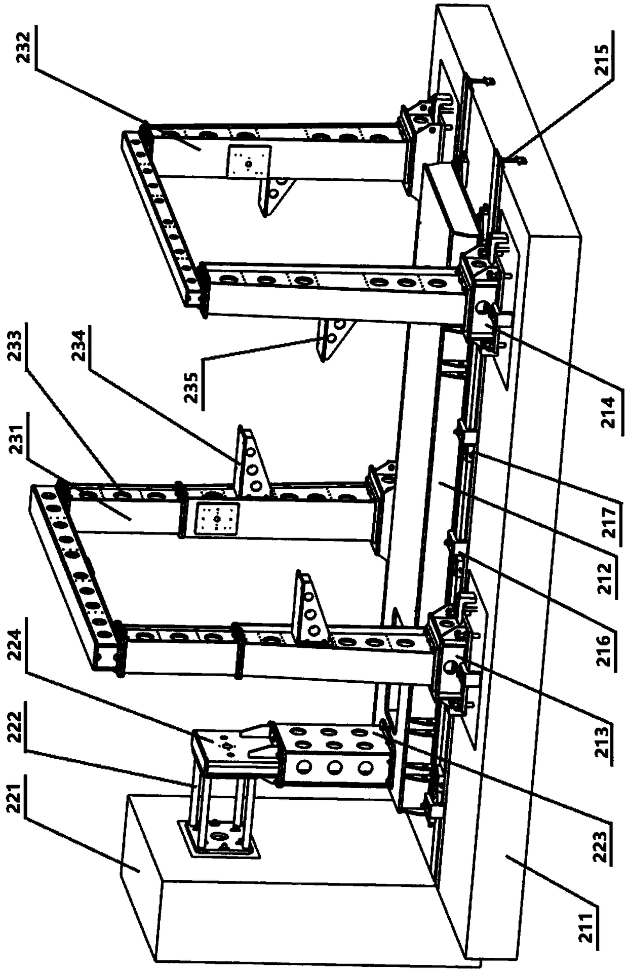
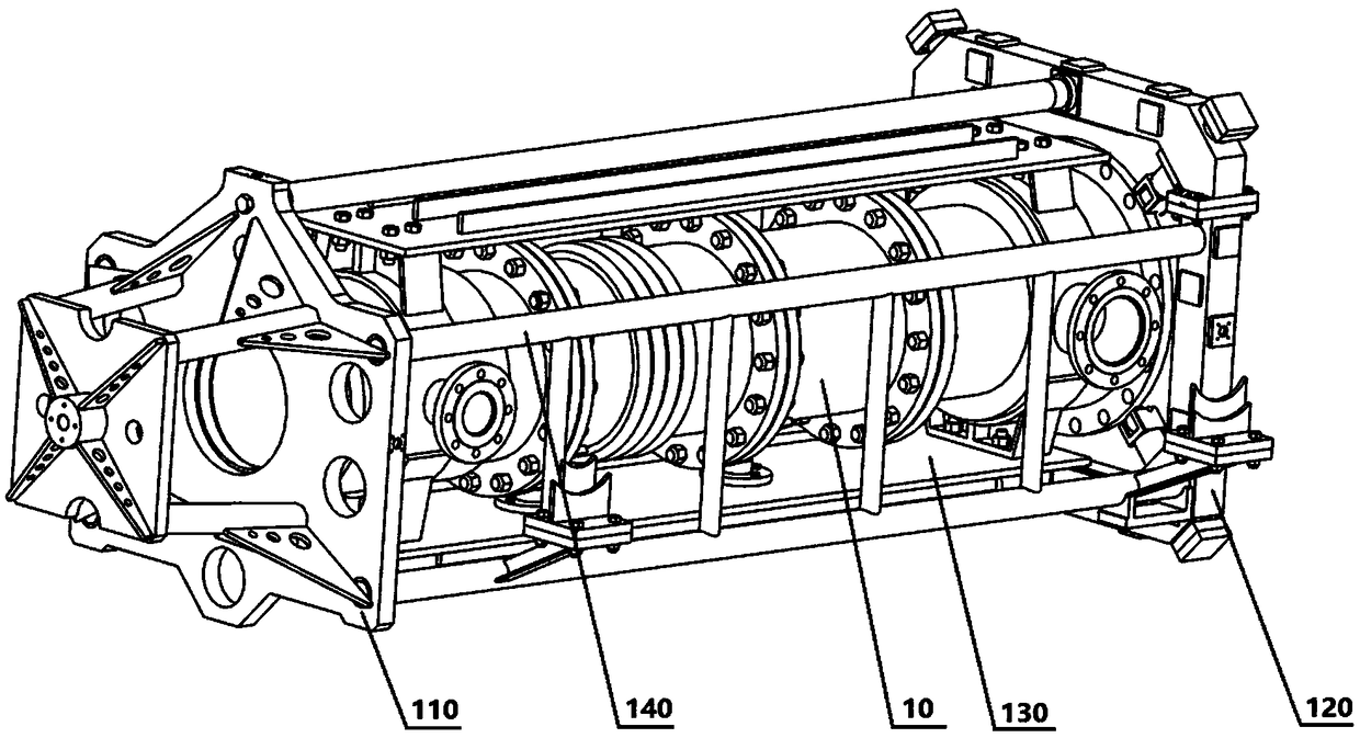
The invention relates to a six-component test stand, which comprises a movable frame, a fixed frame, force measuring assemblies and in-situ calibration devices, wherein the movable frame includes a transfer frame, a center frame, a reinforcement plate and a truss; the fixed frame includes a horizontal foundation part, a force bearing part and an installation part; the horizontal foundation part includes a horizontal base, a horizontal base plate, a first support base and a second support base; the force bearing part includes a force bearing wall, a force bearing frame, a force bearing seat installation base and a force bearing seat; there are a plurality of force measuring assemblies and a plurality of in-situ calibration devices; and the movable frame is connected with the fixed frame through the plurality of force measuring assemblies and the plurality of in-situ calibration devices. The method for measuring the vector thrust comprises the steps of constructing a six-component model,and calculating the vector thrust, the eccentric angle and the eccentric distance of a test piece through a space force system balance equation set according to the six-component model. The six-component test stand is simple in structure. The method for measuring the vector thrust solves a problem of large occupied space of the existing vertical six-component test system. Meanwhile, the gravity of an engine is taken into consideration, and the measurement accuracy is greatly improved.

Description

technical field [0001] The invention relates to the technical field of thrust measurement, in particular to a six-component force test bench and a method for measuring vector thrust. Background technique [0002] Engine testing and testing technology is an important part of solid propulsion technology, and thrust vector eccentricity is an important parameter that needs to be measured in engine testing and testing. To study the eccentricity of the engine thrust vector, a large number of repeated experiments are required, and it is impossible to put all these experiments into flight tests. The main reason is that the flight test has high cost, long period, small amount of information harvested, risky, and requires a lot of manpower. This requires the ground test of the engine. The ground test of the engine refers to the static test of the system on the ground according to specific conditions and environmental requirements, and obtains information describing various performanc...

Claims


Application Information

Patent Timeline
Patent Type & Authority Applications(China)
IPC IPC(8): G01M15/14G01L5/12
CPCG01L5/12G01M15/14
Inventor 周培好陆晓平康宏博
Owner BEIJING AEROSPACE SANFA HIGH TECH
Learn More