High speed visual detection and recognition equipment

A technology for visual inspection and identification equipment, applied in the field of visual inspection and identification, can solve the problems of high cost, low circuit board efficiency, low identification accuracy, etc., and achieve the effect of low cost, simple structure and simplified equipment structure

Active Publication Date: 2019-01-04
深圳智检慧通科技有限公司
View PDF7 Cites 6 Cited by
  • Summary
  • Abstract
  • Description
  • Claims
  • Application Information

AI Technical Summary

Problems solved by technology

[0005] The present invention provides a high-speed visual detection and recognition device for the defects of low efficiency, high cost, and low recognition accuracy in the AOI detection of finished circuit boards in the prior art.

Method used


Image

  • High speed visual detection and recognition equipment
  • High speed visual detection and recognition equipment
  • High speed visual detection and recognition equipment

Examples


no. 1 example

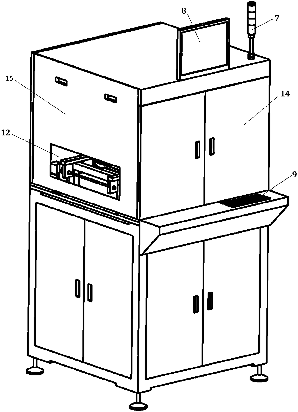
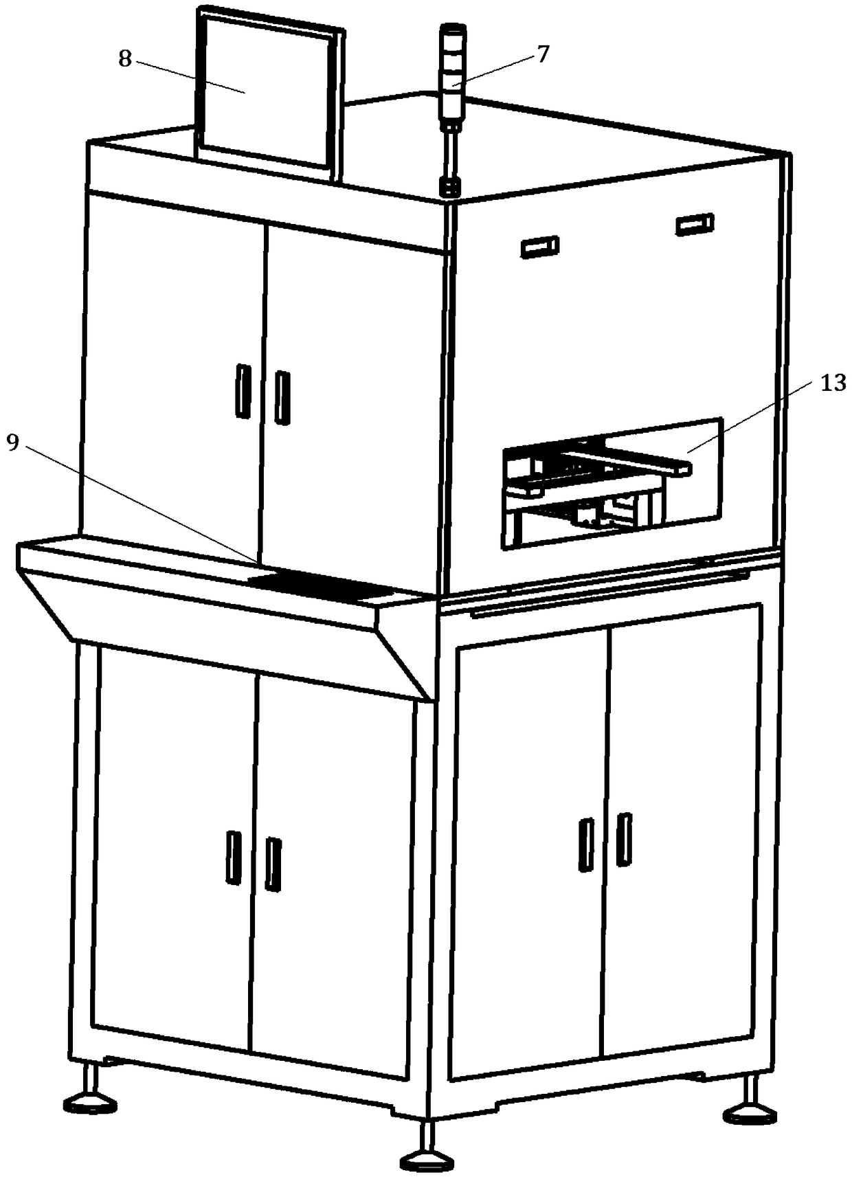
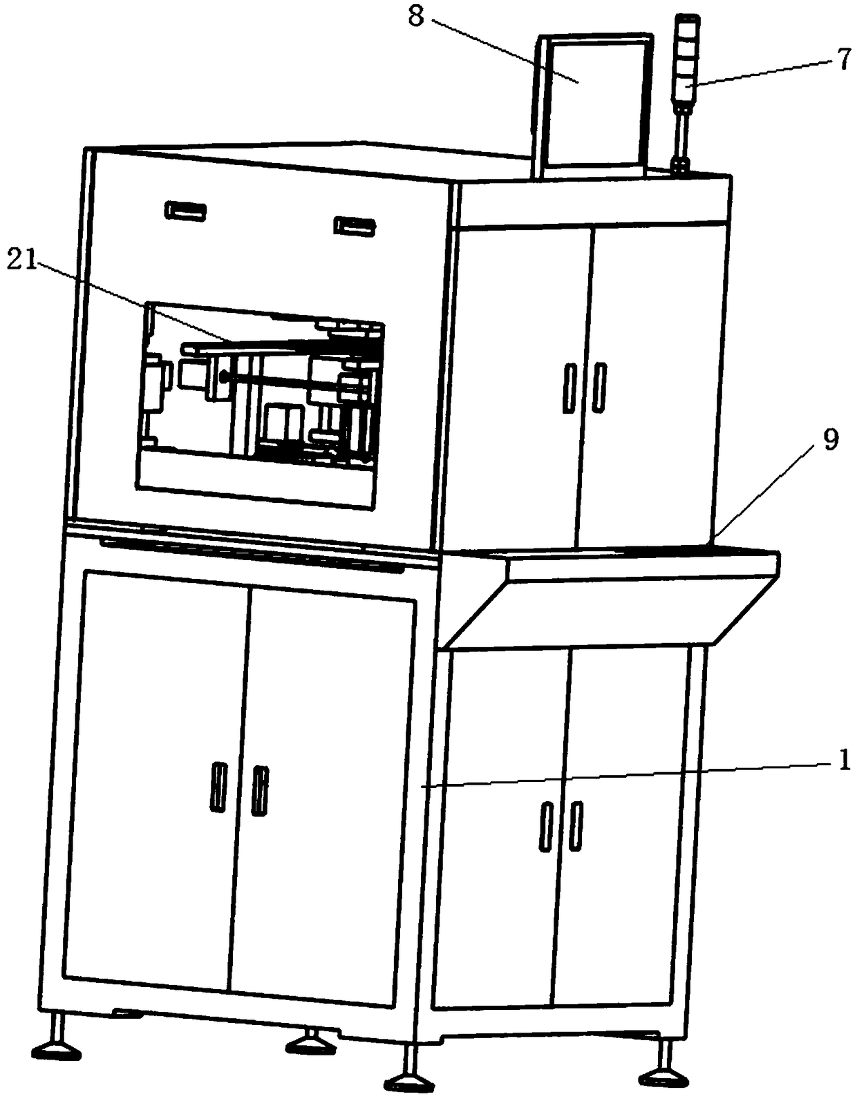
[0041] refer to Figure 1-4 As shown, an embodiment of the high-speed visual inspection and identification device of the present invention is provided, including a main body support 1, a carrying platform 2 arranged in the middle of the main body support 1 for placing and delivering finished circuit boards to be detected and identified, and arranged on the top of the main body support 1 And the first moving mechanism 31 movable along the Y-axis direction, the first photographing device 41 arranged at the lower end of the first moving mechanism 31 for taking images of finished circuit boards, and the first moving mechanism 31 arranged in the main body support 1 and the first photographing device 41 are connected to the control device 6 for controlling.

[0042] refer to Figure 4-7 As shown, it also includes a first Z-axis motion mechanism 314 arranged at the lower end of the first motion mechanism 31 and movable in the Z-axis direction. The first angle adjustment device 315 ...

no. 2 example

[0060] Compared with the first embodiment, this embodiment also includes a fourth movement mechanism 34 arranged at the bottom of the main body support 1 and movable along the Y-axis direction, and a fourth movement mechanism 34 arranged at the upper end of the fourth movement mechanism 34 with the lens facing the finished line The fourth photographing device 44 for photographing the reverse image of the finished circuit board on the reverse side of the board. Its specific structure is the same as that of the first motion mechanism 31, and it can be moved in the Y-axis direction. The fourth motion mechanism 34 is provided with a fourth photographing device 44, so that the image of the reverse side of the finished circuit board can be photographed. In this embodiment It is set that the fourth photographing device 44 is perpendicular to the bottom surface of the finished circuit board to photograph images.

[0061] More specifically, it also includes a second Z-axis motion mecha...


PUM


Abstract

The invention discloses high speed visual detection and recognition equipment. The high speed visual detection and recognition equipment comprises a main body support, a bearing platform, a first moving mechanism, a first shooting device and a control device, wherein the bearing platform is arranged in the main body support and used for placing and conveying to-be-detected and recognized finishedcircular boards; the first moving mechanism is arranged at the top of the main body support and can move in the Y-axis direction; the first shooting device is arranged on the first moving mechanism and used for shooting the finished circuit boards; the control device is arranged in the main body support, is connected with the first moving mechanism and the first shooting device and is used for controlling. The high speed visual detection and recognition equipment disclosed by the invention has the advantages of low quantity of required shooting devices, high degree of automation and high shooting efficiency.

Description

technical field [0001] The invention relates to the technical field of visual detection and recognition, in particular to a high-speed visual detection and recognition device. Background technique [0002] Finished circuit board (Printed Circuit Board + Assembly, referred to as PCBA), that is, the finished circuit board is PCBA, PCBA is one of the key components of electronic equipment. The product does not require this step) to obtain a circuit board, that is, various electronic devices are assembled on the PCB through the surface packaging process. The position of the components on the PCBA, the short circuit of the solder joints and the number of pin headers directly affect the performance and yield of the circuit board. Therefore, PCBA has become an indispensable and very important link to check whether the product is qualified before delivery. [0003] At present, the existing PCBA defect detection and recognition mainly adopts the logical type of automatic optical in...

Claims


Application Information

Patent Timeline
Patent Type & Authority Applications(China)
IPC IPC(8): G01N21/88
CPCG01N21/88Y02P90/30
Inventor 姚霜其他发明人请求不公开姓名
Owner 深圳智检慧通科技有限公司
Why Eureka
Try Eureka