
Transfer device and image forming apparatus

A transfer printing and image technology, which is applied to the electric recording process using the charge pattern, equipment and instruments using the charge pattern electric recording process, etc., can solve the problem of keeping the component toner from scattering not significantly, and achieve the goal of reducing the amount of scattering Effect

Active Publication Date: 2019-01-04
FUJIFILM BUSINESS INNOVATION CORP
View PDF4 Cites 0 Cited by
  • Summary
  • Abstract
  • Description
  • Claims
  • Application Information

AI Technical Summary

Problems solved by technology

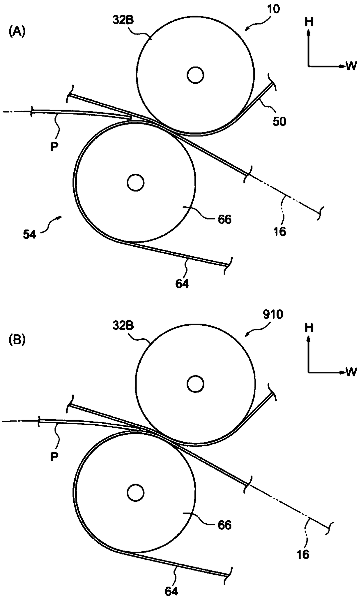
[0005] However, when the base layer formed of toner whose mass is equal to or greater than the threshold value does not become the uppermost layer on the holding member, the scattering of the toner on the holding member is not significant.

Method used


Image

  • Transfer device and image forming apparatus
  • Transfer device and image forming apparatus
  • Transfer device and image forming apparatus

Examples


no. 2 approach

[0136] refer to Figure 17 to Figure 22 , an example of the transfer device and the image forming apparatus according to the second embodiment of the present invention will be described. It should be noted that, regarding the second embodiment, differences from the first embodiment will be mainly described.

[0137] Such as Figure 17 As shown, in the image forming apparatus 410 according to the second embodiment, five color toner layers including yellow (Y), magenta (M), cyan (C), black (K), and silver (V) are provided. The part 30 is formed. In addition, two silver (V) toner layer forming portions 30 are provided. Further, in the circumferential direction of rotation of the transfer belt 50 (see arrow A in the figure), the toner layer forming portion 30 is arranged in the order of silver (V), yellow (Y), magenta (M), and blue from the upstream side. The order of green (C), black (K), and silver (V) is arranged side by side in the horizontal direction.

[0138] -Silver T...

no. 3 approach

[0156] refer to Figure 23 , Figure 24 , an example of the transfer device and the image forming apparatus according to the third embodiment of the present invention will be described. It should be noted that, regarding the third embodiment, differences from the first embodiment will be mainly described.

[0157] Such as Figure 24 As shown, the image forming apparatus 510 according to the third embodiment includes a setting unit 558 that sets the developing device 46 that uses the developer G containing toner to form the image formed on the image holding member 40 ( refer to Figure 23 ) is developed as a toner layer.

[0158] The setting unit 558 sets the developing devices 46W-A, 46W-B so that the first charge amount is greater than the second charge amount. Specifically, the setting section 558 sets the developing devices 46W-A, 46W-B so that the charged amount of toner for developing the electrostatic latent image formed on the image holding member 40W-B is larger t...


PUM


Abstract

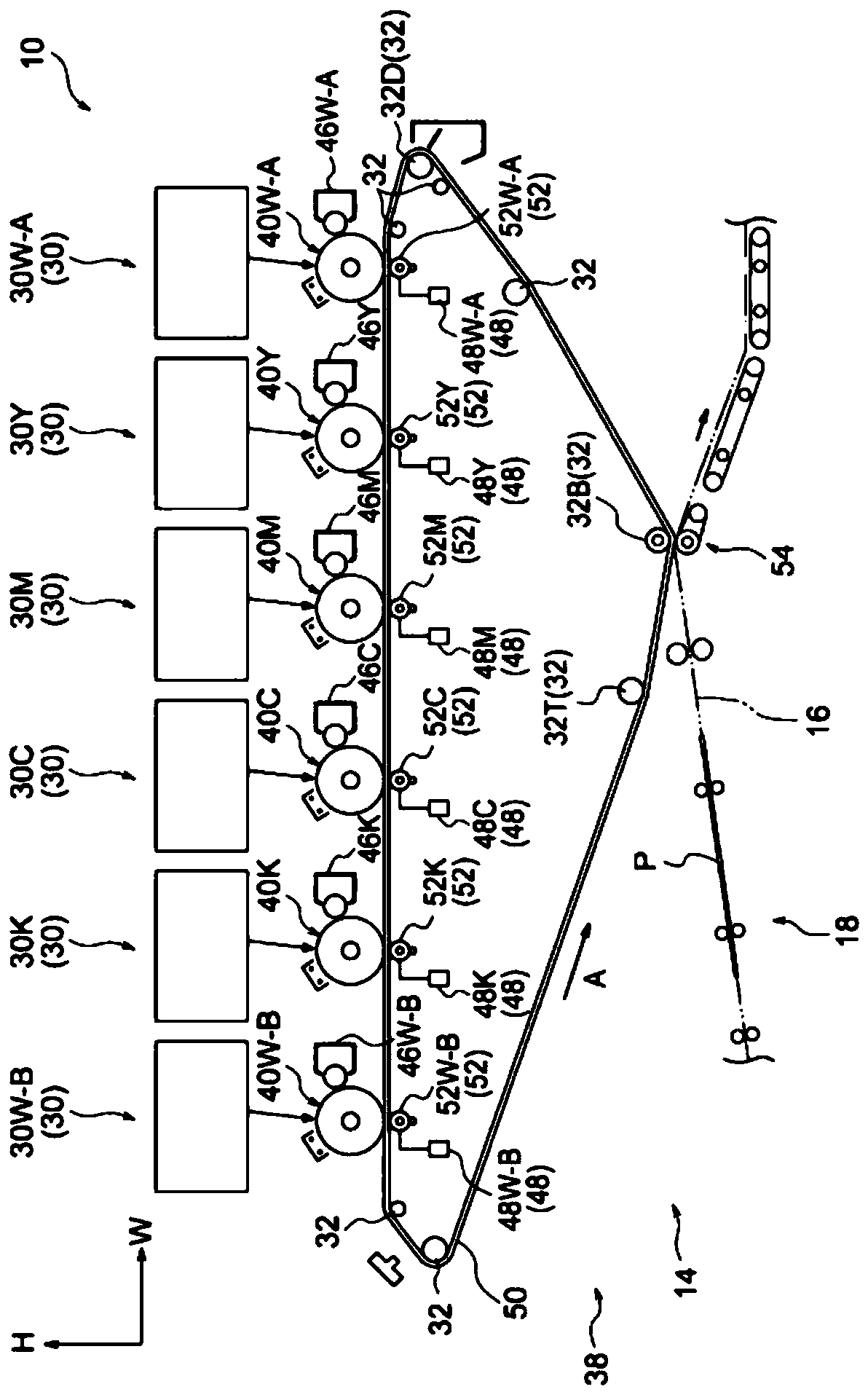
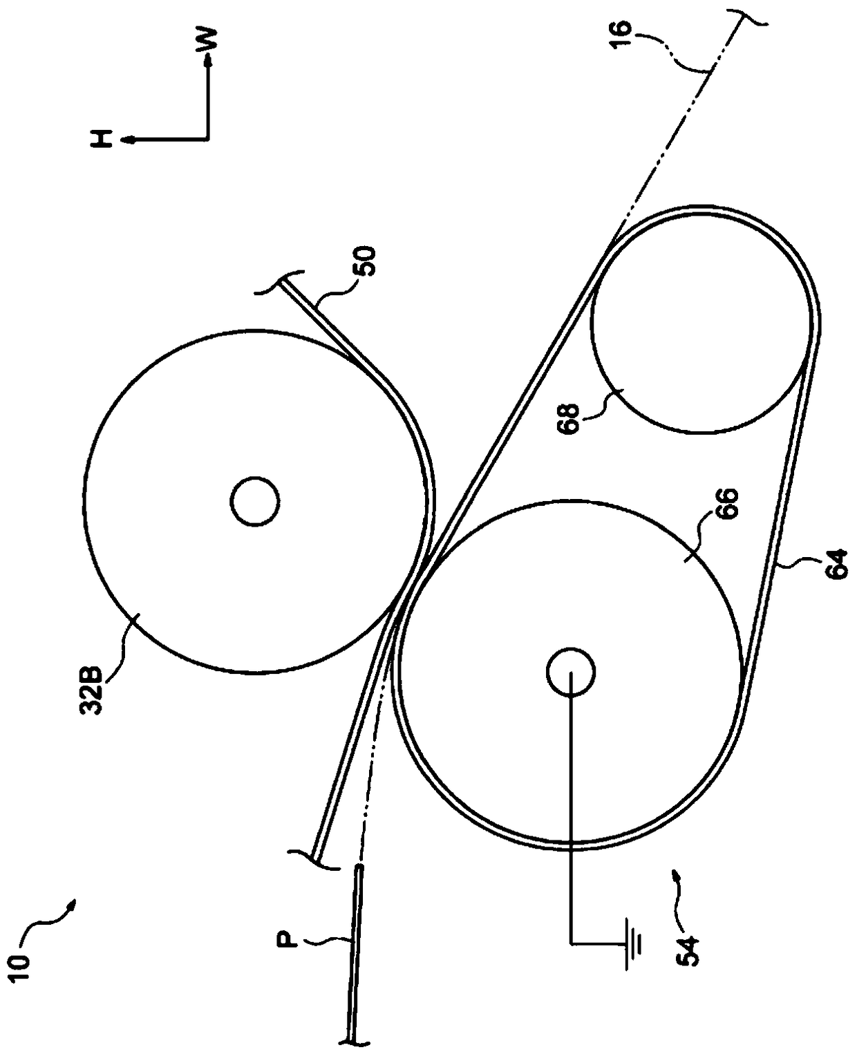
A transfer device includes a holding body, a transfer body, and a setting portion. The holding body holds multiple layers including a base layer formed of a toner having a mass larger than a threshold. The toner is electrically charged by a charging device. The transfer body transfers the layers on the holding body to a recording medium. The setting portion sets the charging device so that the charging device electrically charges a toner immediately after being transferred to the holding body with a larger amount of electric charges when the base layer is located uppermost on the holding body,than when the base layer is located other than uppermost on the holding body.

Description

technical field [0001] The present invention relates to a transfer device and an image forming device. Background technique [0002] In the image forming apparatus described in Japanese Patent Laid-Open No. 2006-154381, the toner developing efficiency of the image forming section located upstream in the rotation direction of the intermediate transfer body is higher than that of the image forming section located downstream. Toner developing efficiency. [0003] The image forming apparatus has a structural member that transfers the toner image on the holding member (transfer belt) to a recording medium after the toner image is transferred by the primary transfer roller onto a holding member (transfer belt) rotating in the circumferential direction. In this image forming apparatus, the transfer unit transfers the toner image on the holding member to the recording medium by conveying the recording medium while pressing the recording medium using a pressing portion (nip portion)...

Claims


Application Information

Patent Timeline
Patent Type & Authority Applications(China)
IPC IPC(8): G03G15/16
CPCG03G15/1665G03G15/161G03G15/169G03G15/18G03G15/0216G03G15/2053G03G15/0808G03G15/0865
Inventor 汤浅宏一郎
Owner FUJIFILM BUSINESS INNOVATION CORP
Learn More