A display panel and a display device

A technology for display panels and substrates, applied in image data processing, instruments, image acquisition, etc., can solve the problems of inability to achieve thin and light display products, and high cost of display panel depth information recognition

Inactive Publication Date: 2019-01-04
BOE TECH GRP CO LTD +1
View PDF12 Cites 11 Cited by
  • Summary
  • Abstract
  • Description
  • Claims
  • Application Information

AI Technical Summary

Problems solved by technology

[0004] The purpose of the embodiments of the present invention is to provide a display panel and a display device to solve the problems of high cost of identifying the depth information of the display panel and the inability to realize light and thin display products

Method used


Image

  • A display panel and a display device
  • A display panel and a display device
  • A display panel and a display device

Examples


no. 1 example

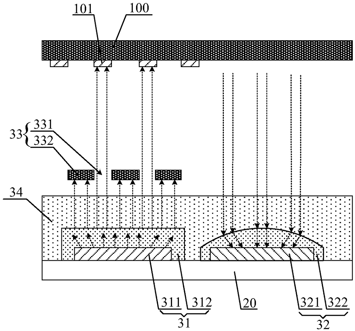
[0042] figure 2 It is a schematic structural diagram of the display panel according to the first embodiment of the present invention. From figure 1 It can be seen from the figure that the display panel in the embodiment of the present invention includes a substrate 20 and a plurality of depth imaging devices, and each depth imaging device is disposed on the substrate 20 . In order to explain the working principle of the depth camera device in more detail, figure 2Only one depth camera device is shown in . The depth camera device includes a light receiving unit 32 and a collimated light source 31 for emitting parallel light. The display panel also includes a shielding layer 33 disposed between the collimated light source 31 and the measured object 100, the shielding layer 33 is provided with a hollow structure 331, and the light emitted by the collimated light source 31 passes through the hollow structure 331 to form a two-dimensional structured light pattern , the two-di...

no. 2 example

[0059] Figure 8 It is a schematic structural diagram of the display panel according to the second embodiment of the present invention. Different from the first embodiment, in this embodiment, if Figure 8 As shown, the display panel further includes a touch electrode layer 51 disposed between the collimated light source 31 and the shielding layer 33 . exist Figure 8 Among them, the touch electrode layer 51 is disposed between the flat layer 34 and the shielding layer 33 . The shielding layer 33 is disposed on the touch electrode layer 51 . It is easy to understand that the touch electrode layer 51 generally includes row electrodes and column electrodes, with gaps between adjacent electrodes. It is easy to understand that the gap between adjacent electrodes includes the gap between adjacent row electrodes, the gap between adjacent column electrodes, and the gap between adjacent row electrodes and column electrodes. In order to ensure that the light emitted by the collima...

no. 3 example

[0063] Based on the inventive concepts of the aforementioned embodiments, an embodiment of the present invention further provides a display device, which includes the display panel of the aforementioned embodiments. The display device can be any product or component with a display function such as a mobile phone, a tablet computer, a television, a monitor, a notebook computer, a digital photo frame, a navigator, and the like.


PUM


Abstract

The invention discloses a display area and a display device. The display panel includes a plurality of depth imaging devices disposed on a substrate and a processor electrically connected to the depthimaging device, the depth imaging device includes a light receiving unit and a collimated light source for emitting parallel light, the display panel further includes a shielding layer disposed between the collimated light source and the object to be measured, the shading layer is provided with a hollow structure, the light emitted by the collimated light source passes through the hollow structure to form a two-dimensional structured light pattern, the light receiving unit receives the reflection pattern of the two-dimensional structured light pattern passing through the object, and the processor obtains the depth information of the object according to the light emitted by the collimated light source and the reflection pattern. The display panel integrates the depth information recognition function and no longer uses the depth camera to obtain the depth information of the object, thus reducing the cost of the display panel and facilitating the lightweight design of the display panel.

Description

technical field [0001] The present invention relates to the field of display technology, in particular to a display panel and a display device. Background technique [0002] With the development of 3D technology, more and more technical applications such as stereoscopic display, machine vision, and satellite remote sensing need to obtain the depth information of the scene. At present, the technical method usually used is to use the depth camera to obtain the depth information of the target in the camera field of view. . [0003] However, the depth camera has the characteristics of large size and high price, so it is difficult to combine with the display products for the purpose of pursuing thinness and lightness. Contents of the invention [0004] The purpose of the embodiments of the present invention is to provide a display panel and a display device to solve the problems of high cost of identifying depth information of the display panel and the inability to realize lig...

Claims


Application Information

Patent Timeline
Patent Type & Authority Applications(China)
IPC IPC(8): G06T7/514G06T7/521G06T1/00
CPCG06T1/0007G06T2207/10028G06T2207/10048G06T7/514G06T7/521
Inventor 任锦宇马国靖
Owner BOE TECH GRP CO LTD
Why Eureka
Try Eureka