Dielectric antenna, dielectric antenna device and communication device

A dielectric antenna and antenna technology are applied in the fields of dielectric antennas, dielectric antenna devices and communication devices, and can solve the problems of antenna characteristic deterioration and characteristic deterioration.

Active Publication Date: 2019-01-04
东莞市合康电子有限公司
View PDF9 Cites 0 Cited by
  • Summary
  • Abstract
  • Description
  • Claims
  • Application Information

AI Technical Summary

Problems solved by technology

In the actual application testing process, the analysis found that the above-mentioned first type of monopole dielectric antenna device can only be used in the corner of the circuit board under normal circumstances, and when this type of monopole dielectric antenna device is far away from the corner position of the circuit board, the antenna characteristics will become worse; the above-mentioned second type of loop dielectric antenna device is usually used in a position far away from the corner, and when used in a corner position, the characteristics will deteriorate, so these two kinds of dielectric antenna devices have certain position restrictions when used

Method used


Image

  • Dielectric antenna, dielectric antenna device and communication device
  • Dielectric antenna, dielectric antenna device and communication device
  • Dielectric antenna, dielectric antenna device and communication device

Examples


Embodiment Construction

[0025] The present invention will be further described below in conjunction with the accompanying drawings.

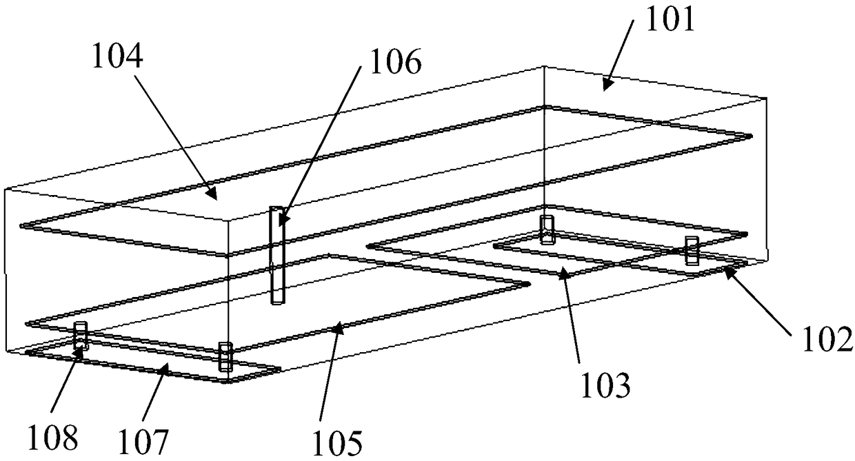
[0026] refer to image 3 , the dielectric antenna of this embodiment includes an antenna body 100, the antenna body 100 includes a dielectric body 101 and a feeding end 102 and a grounding end 107 arranged on the surface of the dielectric body 101, and the antenna body 100 also includes a first Electrode sheet 103, second electrode sheet 105, common electrode sheet 104 and inductance column 106, wherein: first electrode sheet 103 is connected with feed-in end 102, first electrode sheet 103 and common electrode sheet 104 are oppositely arranged and in the first The first capacitor C1 is formed between the electrode sheet 103 and the common electrode sheet 104; the second electrode sheet 105 is connected to the ground terminal 107, and the second electrode sheet 105 is arranged opposite to the common electrode sheet 104, and between the second electrode sheet 105 and the...


PUM


Abstract

A medium antenna include an antenna body, the antenna body comprises a dielectric body and a feed terminal and a ground terminal arranged on the surface of the dielectric body, The antenna body further comprises a first electrode sheet, a second electrode sheet, a common electrode sheet and an inductance post arranged in the dielectric body, wherein, the first electrode sheet is connected with thefeed terminal, and the first electrode sheet and the common electrode sheet are arranged opposite each other to form a first capacitance between the first electrode sheet and the common electrode sheet; The second electrode piece is connected with the ground terminal, A second electrode sheet is opposed to a common electrode sheet to form a second capacitance between the second electrode sheet and the common electrode sheet. Both ends of the inductor post are respectively connected with the common electrode sheet and the ground terminal to form a parallel resonant circuit in parallel with thesecond capacitance. The dielectric antenna can be placed at any position on the circuit board. The invention relates to a dielectric antenna device, wherein the dielectric antenna can be placed in any position of a circuit board; A communication device in which the mounting position of a dielectric antenna on a circuit board is not limited.

Description

technical field [0001] The invention relates to the technical field of antennas, in particular to a dielectric antenna, a dielectric antenna device and a communication device. Background technique [0002] Miniaturized dielectric antenna devices are widely used in mobile terminal equipment such as Bluetooth and WiFi, and have the characteristics of small size, low price and wide application. The dielectric antenna in the dielectric antenna device is usually passed on the surface of a medium with a certain dielectric constant or a medium It is realized by forming a specific metal pattern inside. At present, there are two main types of miniaturized dielectric antenna devices: the first type is similar to a monopole antenna device, and the end of the antenna body is open to the ground. Theoretically, the size of a monopole antenna is 1 / 4 One wavelength, the dielectric antenna device can be loaded by the medium to reduce the size of the dielectric antenna, the equivalent circuit...

Claims


Application Information

Patent Timeline
Patent Type & Authority Applications(China)
IPC IPC(8): H01Q23/00H01Q1/38H01Q1/48H01Q1/50
CPCH01Q1/38H01Q1/48H01Q1/50H01Q23/00
Inventor 尹志强
Owner 东莞市合康电子有限公司
Why Eureka
Try Eureka