
Power supply control system and method

A technology of power control and power controller, which is applied in the direction of data switching current source, electrical components, advanced technology, etc., can solve the problems of inability to supply power to equipment, equipment power supply closure, etc., and achieve the effect of reducing life loss and saving power costs

Inactive Publication Date: 2019-01-04
MAIPU COMM TECH CO LTD
View PDF10 Cites 4 Cited by
  • Summary
  • Abstract
  • Description
  • Claims
  • Application Information

AI Technical Summary

Problems solved by technology

[0008] The above-mentioned timing strategy can solve the problem of device power supply closure for some fixed service hours (such as: the service time is 8:00am-18:00pm), but it cannot supply power to the device on demand according to the surrounding traffic conditions.

Method used


Image

  • Power supply control system and method
  • Power supply control system and method
  • Power supply control system and method

Examples


Embodiment

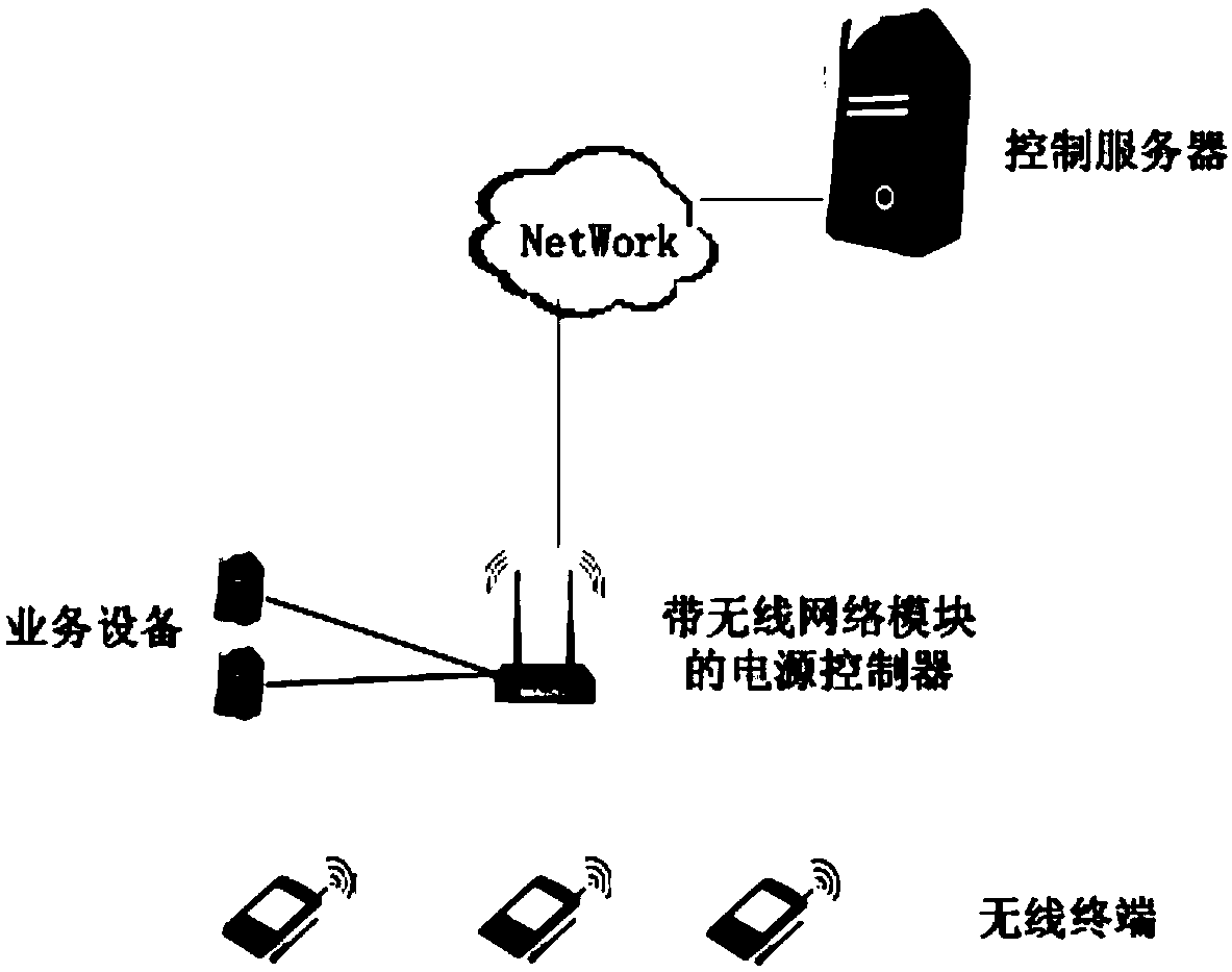
[0062] This embodiment will describe the interaction process of wireless terminals, wireless network modules, power controllers, business equipment and control servers in the power control scheme, as follows:

[0063] 1) The power controller registers to the control server through the network.

[0064] 2) The control server sends power control rules to the power controller, wherein the power control rules include: power off threshold Mmin, power on threshold Mmax, wireless scanning frequency band FList, and wireless network module statistics cycle RI.

[0065] 3) The power controller activates the power control rules.

[0066] 4) The power controller sends the wireless scanning frequency band FList and the statistical period RI of the wireless network module to the wireless network module.

[0067] 5) The wireless network module listens to Probe Requests initiated by all wireless terminals within the frequency range FList, and counts the number MC of the MAC addresses of the ...


PUM


Abstract

The invention relates to power supply control technologies, and discloses a power supply control system. The system can save electric power costs and supply power for service equipment according to the flow of people around and demands. The system includes a control server and a power supply controller; the control server is used for configuring power supply control rules for the power supply controller and issues the rules to the power supply controller; the power supply controller is configured with a wireless network module, and the wireless network module is used for scanning the number ofwireless terminals within an assigned frequency range and cyclically reports the number of the wireless terminals to the power supply controller; and the power supply controller performs comparison on the number of the wireless terminals and the threshold values in the power supply control rules, and the opening or closing of the power supply output port connected to the service equipment can becontrolled according to comparison results. In addition, a power supply control method is also disclosed, and is suitable for the controlling of the power supply of the service equipment according todemands.

Description

technical field [0001] The invention relates to power control technology, in particular to a power control system and method. Background technique [0002] In the current field of power control, it is usually controlled by manual or timing mechanism to close the power supply. However, in some practical applications, business equipment only needs power supply when there are potential users around, and does not need power supply to run at other times. If the business The equipment has been running empty, which is likely to cause waste of electricity and reduce the service life of business equipment. Therefore, it is necessary to dynamically control the closing of the power supply of the service equipment. [0003] In the traditional technology, the scheme that needs to dynamically control the closing of the power supply usually adopts a timing strategy. The control system mainly involves two parts: the upper-end control system and the power supply controller. The control meth...

Claims


Application Information

Patent Timeline
Patent Type & Authority Applications(China)
IPC IPC(8): H04W8/00H04L12/10
CPCH04L12/10H04W8/005Y02D30/70
Inventor 刘成双
Owner MAIPU COMM TECH CO LTD
Learn More