Indexable Drilling Tool

A drilling tool and indexing technology, which is applied in drilling tool accessories, drilling/drilling equipment, drilling repair, etc., can solve the problem of difficult radial force balance between inner and outer blades, easy cutting vibration, and processing Problems such as poor surface quality

Active Publication Date: 2020-02-04
ZHUZHOU CEMENTED CARBIDE CUTTING TOOLS CO LTD
View PDF7 Cites 0 Cited by
  • Summary
  • Abstract
  • Description
  • Claims
  • Application Information

AI Technical Summary

Problems solved by technology

[0002] The cutting edge of the indexable drilling tool is asymmetrical with respect to the central axis. Its cutting part includes two kinds of blades, the inner blade and the outer blade. In the area of ​​material removal, the outer blade completes the removal of peripheral material, while the linear velocity of the cutting edge of the drilling tool increases with the increase of the radius. Therefore, the linear velocity of the central area of ​​the inner blade is close to zero, and the central area of ​​the drilling tool cuts The edge friction is severe, and the material removal amount of the cutting edge adjacent to the peripheral surface of the cutter body is much larger than that of the center. In order to meet the requirements of different cutting conditions of the inner and outer blades, in the prior art, the inner and outer blades usually have different structures or It has the same structure but adopts different installation dimensions. Although the combination of wear and impact resistance of the inner blade and outer blade can be improved to a certain extent through the above structure, due to the independence of the inner and outer blades installed on the cutter body, As a result, when the inner and outer blades participate in the cutting, the radial force of the tool is difficult to balance, and the unbalanced cutting force is likely to generate cutting vibration, which not only reduces the quality of the machined surface and the dimensional accuracy of the hole, but also makes the indexable drilling tool greatly reduced lifespan
[0003] In order to achieve a certain balance between the radial cutting forces of the inner and outer blades, in the prior art, by changing the cutting width of the inner and outer blades and distributing the inner and outer blades at an asymmetrical phase angle in the circumferential direction of the cutter body, thereby The cutting force of the inner and outer blades is distributed reasonably in the radial direction. However, in order to ensure the cutting stability of the inner and outer blades when they cut into the workpiece during the drilling process, the main cutting edges of the inner and outer blades do not cut into the workpiece at the same time, but The radial balance of the inner and outer blades is not only affected by the cutting force but also directly related to the degree of inclination of the inner and outer blades; more importantly, because the wear of the inner and outer blades is not synchronized, the wear Asynchronous changes of the blade may also upset the balance between the inner and outer blades
Radial balance refers to the double radial balance of radial balance in the cutting plane and radial balance in the end plane. Although the above technical means can theoretically solve the radial balance problem of the inner and outer blades, but due to the cutting edge of the inner and outer blades The shape, inclination angle, installation angle and rake angle and other structural dimensions are different. In the actual processing process, it is difficult to achieve the radial force balance between the inner blade and the outer blade, so that cutting vibration is easy to occur during cutting, resulting in the processed Large hole diameter deviation, poor surface quality, and inner and outer blades are prone to chipping

Method used


Image

  • Indexable Drilling Tool
  • Indexable Drilling Tool
  • Indexable Drilling Tool

Examples


Embodiment Construction

[0034] The present invention will be further described in detail below in conjunction with the accompanying drawings and specific embodiments.

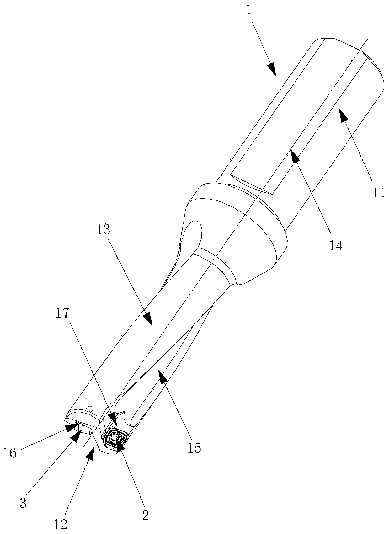
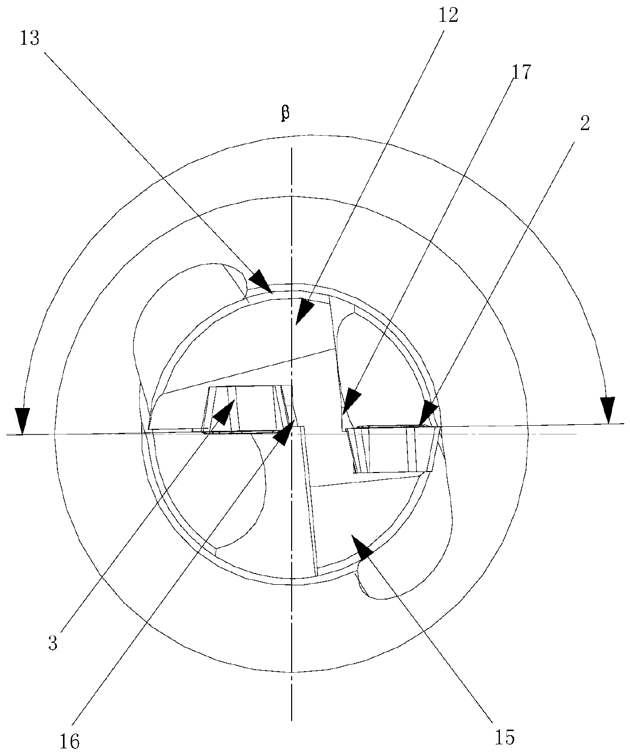
[0035] Figure 1 to Figure 5 The first embodiment of the indexable drilling tool of the present invention is shown. The indexable drilling tool of this embodiment includes a cutter body 1, an outer blade 2 and an inner blade 3. The cutter body 1 includes a shank 11, a cutting The end portion 12 and the peripheral surface 13 between the shank portion 11 and the cutting end portion 12, the shank portion 11 and the peripheral surface 13 are all symmetrical about the rotation center axis 14 of the cutter body 1, and the cutting end portion 12 is provided with the peripheral surface 13. The central groove 16 and the circumferential groove 17 connected by the spiral groove 15 on the top, the central groove 16 is arranged adjacent to the rotation center axis 14, the circumferential groove 17 is arranged adjacent to the peripheral surface 13,...


PUM


Abstract

The invention discloses an indexable drilling tool. The indexable drilling tool is characterized in that an inner blade is composed of a first upper surface, a first lower surface and a first side surface which is used for connecting the first upper surface with the first lower surface in a surrounding mode, the first upper surface and the first side surface intersect to form a plurality of identical inner cutting edges, during drilling machining, the cutting areas of the inner cutting edges serving as main cutting edges are located between middle inner points and middle outer points on the inner cutting edges, the cutting areas of outer cutting edges serving as main cutting edges are located between peripheral inner points and peripheral outer points on the outer cutting edges, in the feeding direction of the indexable drilling tool, an inner convex cutting part with the maximum cutting depth on the inner cutting edges and the outer cutting edges is arranged between the middle inner points and the middle outer points, the depth differences of the middle inner points and the peripheral outer points relative to the inner convex cutting part are correspondingly H1 and H2, and H1 andH2 should meet the following conditions that H1 is larger than or equal to 0.9H2 and less than or equal to 1.1H2. The indexable drilling tool has the following advantages that the cutting vibration issmall, the radial balance capability, is strong, the machining surface quality is good, and the size precision is high.

Description

technical field [0001] The invention relates to the technical field of metal cutting, in particular to an indexable drilling tool. Background technique [0002] The cutting edge of the indexable drilling tool is asymmetrical with respect to the central axis. Its cutting part includes two kinds of blades, the inner blade and the outer blade. In the area of ​​material removal, the outer blade completes the removal of peripheral material, while the linear velocity of the cutting edge of the drilling tool increases with the increase of the radius. Therefore, the linear velocity of the central area of ​​the inner blade is close to zero, and the central area of ​​the drilling tool cuts The edge friction is severe, and the material removal amount of the cutting edge adjacent to the peripheral surface of the cutter body is much larger than that of the center. In order to meet the requirements of different cutting conditions of the inner and outer blades, in the prior art, the inner ...

Claims


Application Information

Patent Timeline
Patent Type & Authority Patents(China)
IPC IPC(8): B23B51/00
CPCB23B51/00
Inventor 王社权江爱胜李勋汤爱民项兴东王鹏
Owner ZHUZHOU CEMENTED CARBIDE CUTTING TOOLS CO LTD
Why Eureka
Try Eureka