Dismantling-free tire repair gun for automobile vacuum tire
A vacuum and tire technology, applied in the field of non-dismantling tire repair gun, can solve the problems of time-consuming repair, failure to repair tires, secondary tire damage, etc.
- Summary
- Abstract
- Description
- Claims
- Application Information
AI Technical Summary
Problems solved by technology
Method used
Image

Examples
Embodiment 1
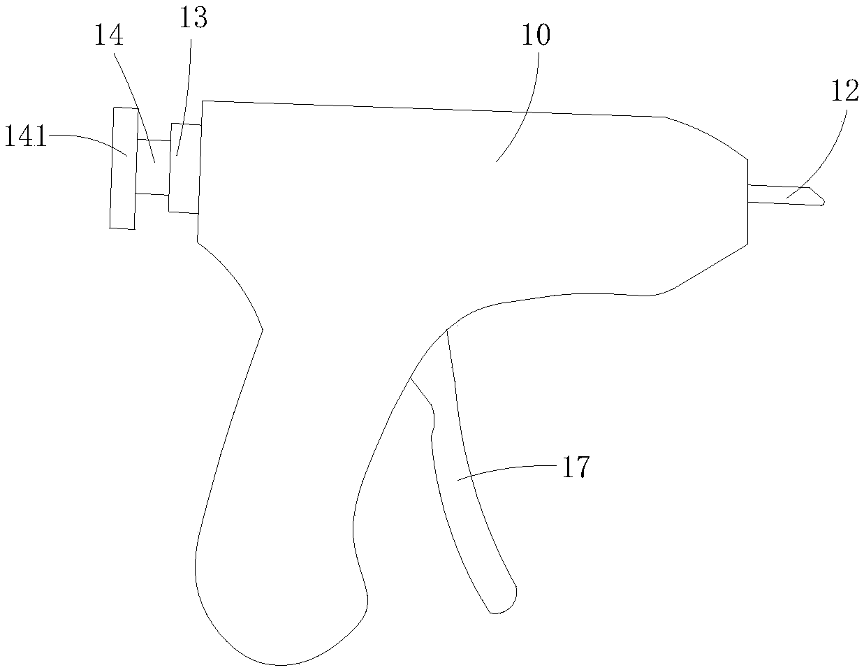
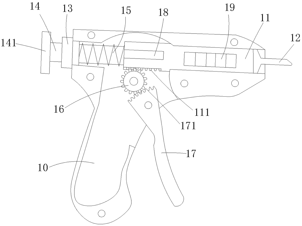
[0013] Example 1, see figure 1 and figure 2 Shown: a kind of free tire repair gun that is used for automobile vacuum tire, comprises gun body 10 and gun barrel 11, and gun body 10 is generally made of aluminum or hard plastic, and it is made of left gun body and right gun body Composed, and the inside has a gun passage, and the gun barrel 11 is arranged in the gun passage; a limit end surface that limits the slide of the gun barrel 11 is provided in the gun body 10, and the limit end surface can be a step, or a slope from wide to narrow. Gun barrel 11 is generally made of steel, is provided with electric heating device on gun barrel 11, and electric heating device is made of heating sheet 19, power lead wire and electric control switch, and heating sheet 19 is positioned at the peripheral surface of gun barrel 11, and electric heating device The control switch is located on the gun body 10, and the power lead is electrically connected to the heating plate 19 through the elec...
Embodiment 2
[0014] Embodiment 2, embodiment 2 is roughly the same as embodiment 1, and its difference is: the structure of limit mechanism is: be provided with chute on gun body 10, be provided with positioning pin on gun barrel 11, and positioning pin Positioned in the chute; it can also achieve the effect in embodiment 1.
PUM
 Abstract
Description
Claims
Application Information