In-situ test device and method for testing shear strength and long-term creep deformation of rock sample

A technology of shear strength and creep deformation, applied in the direction of applying stable shear force to test material strength, mechanical solid deformation measurement, etc., can solve the problems affecting the accuracy of test results, uneven force on the shear surface, shear Problems such as poor process stability, to achieve the effect of more reliable test results, low cost, and uniform force

Active Publication Date: 2019-01-08
重庆市璧山区江源机械有限公司
View PDF10 Cites 21 Cited by
  • Summary
  • Abstract
  • Description
  • Claims
  • Application Information

AI Technical Summary

Problems solved by technology

[0005] The above two methods are difficult to provide accurate and constant vertical pressure for the test, and the stability is poor during the shearing process, and the force on the shearing surface is uneven

Method used


Image

  • In-situ test device and method for testing shear strength and long-term creep deformation of rock sample
  • In-situ test device and method for testing shear strength and long-term creep deformation of rock sample
  • In-situ test device and method for testing shear strength and long-term creep deformation of rock sample

Examples


Embodiment 1

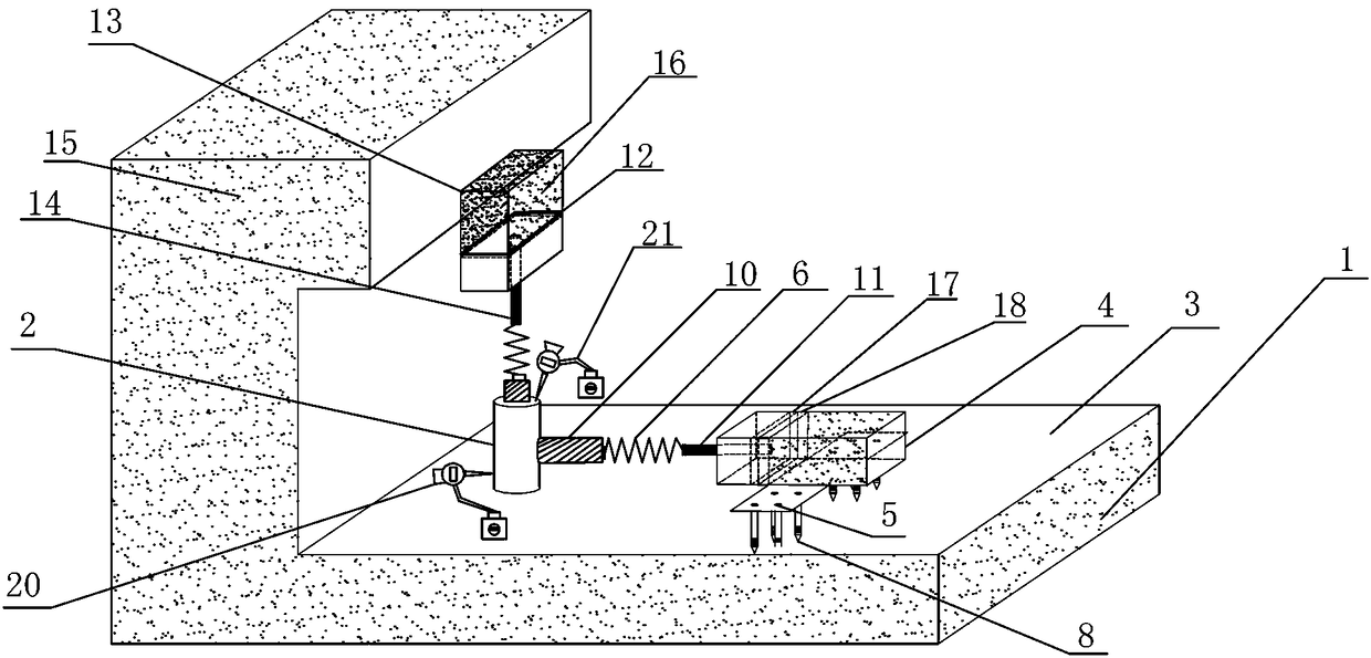
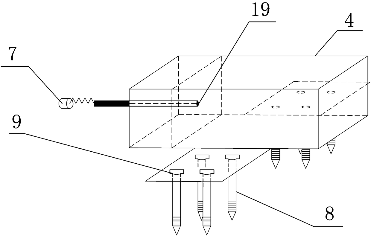
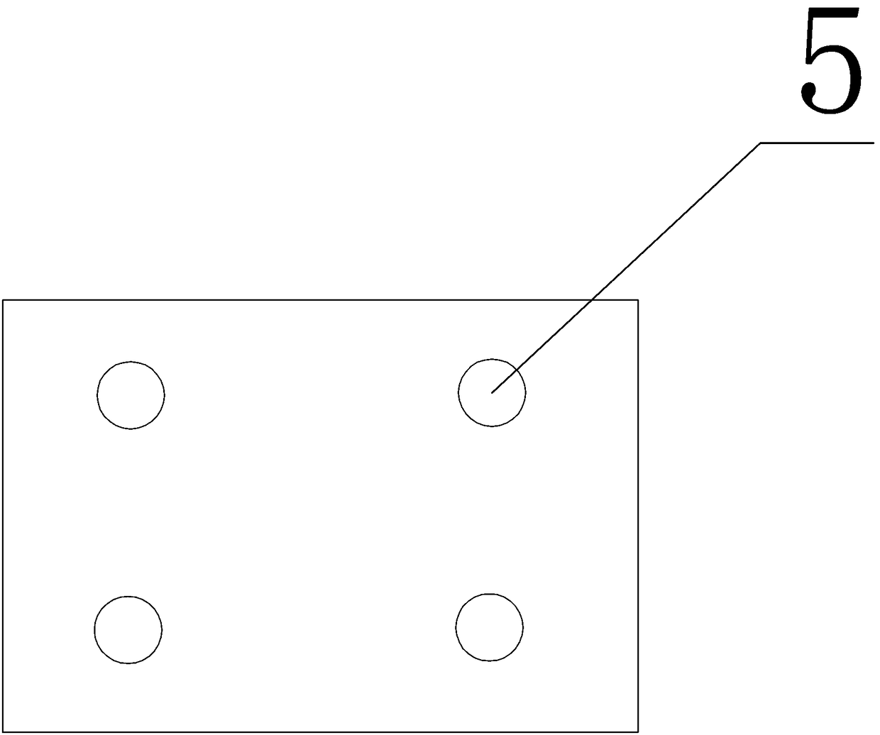
[0052] An in-situ test device for testing the shear strength and long-term creep deformation of a rock sample, which includes a surrounding rock 1 and a rock sample 2 to be sheared, and a horizontal shear box 4 is fixed on a flat surrounding rock surface through a threaded ground anchor 8 3. In the horizontal shear box 4 and the vertical load loading box 16, pour the expansion cement slurry 13 with a large amount of expansion agent, and the expansion force generated can pass through the force transmission plate 12 of the dumbbell-shaped shear bar 7, the dowel bar 11, and the Adjust the butterfly spring 6 and the loading probe 10 to apply vertical load and horizontal shear load on the rock sample 2 to be sheared, and monitor the data in the test process through the pressure sensor 19 and the shear displacement percentage meter 20 to draw the shear stress The relationship curve between the normal stress and the shear strength parameters of the rock mass on the specific failure su...

Embodiment example 2

[0074] Any in-situ testing device and method for testing rock sample shear strength and long-term creep deformation is characterized in that it includes the following steps:

[0075] Step1: Clean up the surrounding rock: select the surrounding rock surface with better lithology, and clean up the weeds and gravel on the surrounding rock to be cut;

[0076] Step2: Cutting rock samples and test platform: Use cutting equipment to cut and grind an over-excavation test platform, which is in the shape of a concave regular hollow cube, including sheared rock samples, flat surrounding rock surfaces and upper surrounding rocks, rocks to be sheared Sample size is 70cmx70cmx70cm;

[0077] Step3: Prefabricated horizontal shear box and vertical load loading box: According to the appropriate size, use a relatively strong steel plate to weld a cuboid without a top cover, and weld a steel plate with a protruding central opening on one side steel plate, which is the horizontal shear Box-cut an...


PUM

PropertyMeasurementUnit
Shear areaaaaaaaaaaa

Abstract

The invention discloses an in-situ test device and method for testing the shear strength and long-term creep deformation of a rock sample. A test platform is cut in a region where the surrounding rockis located, and a shear rock sample, a flat surrounding rock surface and an upper surrounding rock are arranged on the surrounding rock; a horizontal shear box is arranged at the top of the flat surrounding rock surface and on a side of the shear rock sample; a horizontal shear device is arranged between the horizontal shear box and a side wall of the shear rock sample; a vertical load loading box is arranged on the lower end surface of the upper surrounding rock, and a vertical shear device is arranged between the lower end surface of the vertical load loading box and the shear rock sample;the horizontal shear device and the vertical shear device are of the same structure, and are powered by expanded cement slurry. The self-expansion property of the expansion agent is innovatively usedto provide a load source for in-situ shear test on site, and the expansion load is transmitted to the on-site rock sample through a loading probe of a dumbbell-shaped shear rod by means of expansion force generated by the expanded cement slurry to measure a shear strength index on a specific shear plane.

Description

technical field [0001] The invention relates to an in-situ shear test and a direct shear test device for rock samples under vertical load conditions in geotechnical engineering, in particular to an in-situ test device and method for testing the shear strength and long-term creep deformation of rock samples . Background technique [0002] The shear test of rock under compression conditions is the basic method to obtain the peak shear strength and residual strength of rock under different normal pressures, and it is also an important means to obtain the shear strength parameters of rock. Therefore, it has been widely used in geotechnical engineering, and different compression-shear test equipment has been developed. Common equipment includes large direct shear instruments used in laboratory tests and small portable direct shear instruments used in field in situ tests. [0003] The existing indoor compression-shear test equipment is relatively complicated, including the bondi...

Claims


Application Information

Patent Timeline
IPC IPC(8): G01N3/24G01B5/30
CPCG01B5/30G01N3/24
Inventor 刘杰兰俊高素芳周文俊高进张罗送孙涛黎照阳菲李骁霖罗越文韩绍康周克虎姜锋武杰宾莫承林蒋旭
Owner 重庆市璧山区江源机械有限公司
Why Eureka
Try Eureka