Sheet metal and sheet metal strip shearing system with variable speed feeding device

A metal strip and material feeding technology, which is applied to metal processing equipment, shearing devices, shearing machine equipment, etc., can solve the problems of severe fluctuations in the maneuvering load of flying shears, unfavorable length control accuracy, etc., and achieve the elimination of double length, The effect of sizing control model simplification and fast shearing speed

Inactive Publication Date: 2002-10-02
XIAN HEAVY DUTY MACHINERY INST MINIST OF MACHINE BUILDING
View PDF5 Cites 0 Cited by
  • Summary
  • Abstract
  • Description
  • Claims
  • Application Information

AI Technical Summary

Problems solved by technology

[0003] The purpose of the present invention is to provide a metal sheet strip flying shear with variable speed feeding to solve the problems in the prior art that the motor load of the flying shear fluctuates seriously, which is not conducive to rapid shearing and the control operation model is relatively complicated, which is not conduci

Method used


Image

  • Sheet metal and sheet metal strip shearing system with variable speed feeding device
  • Sheet metal and sheet metal strip shearing system with variable speed feeding device
  • Sheet metal and sheet metal strip shearing system with variable speed feeding device

Examples


Embodiment Construction

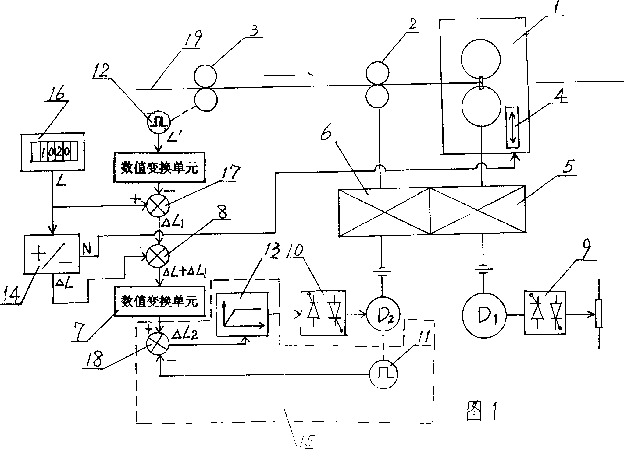
[0019] Referring to Fig. 1, this system comprises flying shear machine 1, feeding roller 2, measuring roller 3, dragging the motor D1 of flying shear machine operation and the driver 9 of motor D1, the adjustment motor D2 of feeding roller and the driver 10 of motor D2, main Transmission mechanism 5, differential mechanism 6 and electrical control system. The flying shear 1 has a definite rotary motion track and an air-cutting control mechanism 4, and its rotary motion track can be circular or non-circular.

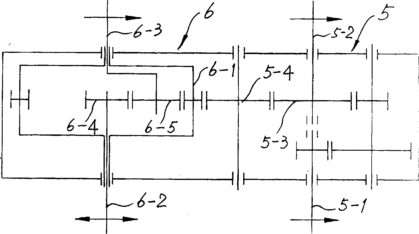
[0020] see figure 2 , the main transmission mechanism 5 adopts a common gear reducer, and the differential mechanism 6 adopts a typical planetary gear differential mechanism. The input end 5-1 of the gear reducer is connected to the motor D1, and its output end 5-2 is connected to the flying shear 1, and the output gear 5-3 of the gear reducer is used as a motion input member of the planetary gear differential mechanism , it meshes with the outer ring gear 6-1 in the pl...


PUM


Abstract

A metal plate and strap fly-shearing system includes rotating flying shears, main driving mechanism, motor D1 for driving flying shears and driver for driving motor D1, feeding roller, differential mechanism, motor D2 for regulating feeding roller and driver for driving motor D2 and electric control system which includes operation unit for calculating cut length and defining regulation mode and closed-loop regulation actuating unit for regulating angle displacement of motor D2. Said invention utilizes the differential mechanism to make synchronous shearing control and cut control separating so as to simplify electric control model and raise shearing speed and cut control accuracy.

Description

Technical field: [0001] The invention relates to a metal strip flying shear system with variable speed feeding, which is used for cutting the metal strip to a fixed length. Background technique: [0002] At present, there is a rotary flying shear system publicly used in China, as shown in Fig. 3, which consists of a rotary flying shear machine 1, a feeding roller 2, a measuring roller 3, a motor D1 for dragging the flying shear machine, and a driver 9 for the motor D1, The motor D2 that drags the feeding roller, the driver 10 of the motor D2 and the electrical control system 20 that controls the operation of the entire flying shear system are composed. When the flying shear system is working, the motor D2 drives the feed roller to rotate, and the feed roller pinches the strip 19 to move forward at a constant speed, and the moving strip drives the measuring roller 3 to rotate by means of friction. The speed signal given by the system drags the clipper 1 to run. Described fl...

Claims


Application Information

Patent Timeline
IPC IPC(8): B23D17/00B23D25/12B23D36/00
Inventor 周德奇张勇安王社昌任玉成
Owner XIAN HEAVY DUTY MACHINERY INST MINIST OF MACHINE BUILDING
Why Eureka
Try Eureka