Method for preventing peritoneal dialysis tube from floating and peritoneal dialysis tube with fixed end

A peritoneal dialysis tube and a dialysis tube technology are applied in the field of peritoneal dialysis tubes, which can solve the problems of being easily squeezed in the abdominal cavity and unable to perform accurate operations, and achieve the effects of preventing drifting tubes, accurately operating and positioning, and accurately operating and correcting

Inactive Publication Date: 2019-01-11
THE SECOND PEOPLES HOSPITAL OF NANTONG
View PDF0 Cites 5 Cited by
  • Summary
  • Abstract
  • Description
  • Claims
  • Application Information

AI Technical Summary

Problems solved by technology

Most of these are performed under external environmental conditions, cannot be operated accurately, an

Method used


Image

  • Method for preventing peritoneal dialysis tube from floating and peritoneal dialysis tube with fixed end
  • Method for preventing peritoneal dialysis tube from floating and peritoneal dialysis tube with fixed end
  • Method for preventing peritoneal dialysis tube from floating and peritoneal dialysis tube with fixed end

Examples


Embodiment

[0031] The following is attached Figure 1-6 The present invention is described in further detail.

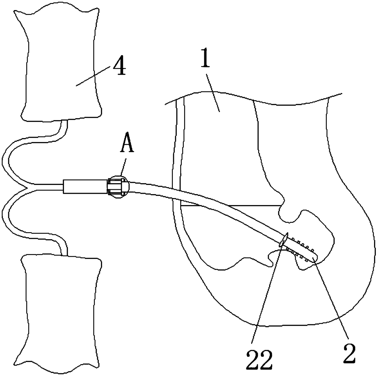
[0032] A method for preventing peritoneal dialysis tube from drifting and a peritoneal dialysis tube with a fixed end, such as Figure 1-2 As shown, including the abdominal cavity 1, the interior of the abdominal cavity 1 is provided with an external dialysis tube 2, one end of the external dialysis tube 2 extends to the outside of the abdominal cavity 1, and the inner wall of the external dialysis tube 2 is slidably inserted into an inner dialysis tube 3, and the inner dialysis tube 3 One end of the outer dialysis tube 2 is extended to the outside of one end of the outer dialysis tube 2 , and one end of the inner dialysis tube 3 is fixedly connected with a dialysate bag 4 .

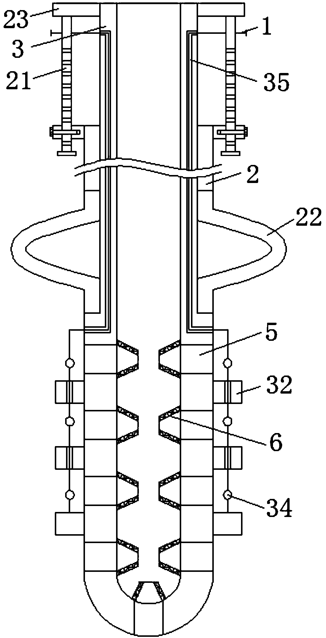
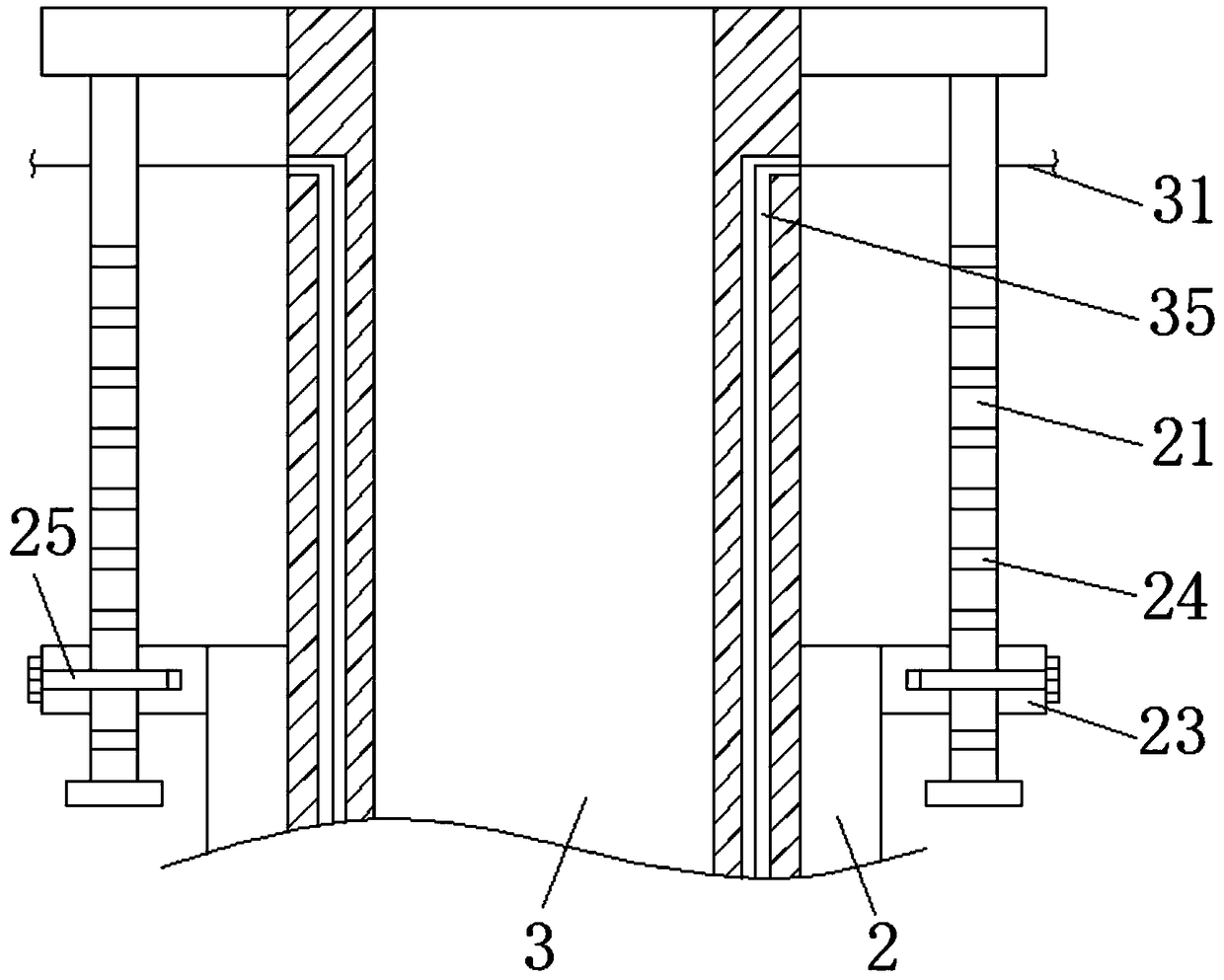
[0033] Figure 2-4 As shown, an adjustment device is fixedly connected to one end of the outer dialysis tube 2 and the inner dialysis tube 3. The adjustment device includes a sliding rod 21 and a silico...

Embodiment 1

[0037]A method for preventing peritoneal dialysis tube from drifting and a peritoneal dialysis tube with a fixed end, such as Figure 1-2 As shown, including the abdominal cavity 1, the interior of the abdominal cavity 1 is provided with an external dialysis tube 2, one end of the external dialysis tube 2 extends to the outside of the abdominal cavity 1, and the inner wall of the external dialysis tube 2 is slidably inserted into an inner dialysis tube 3, and the inner dialysis tube 3 One end of the outer dialysis tube 2 is extended to the outside of one end of the outer dialysis tube 2 , and one end of the inner dialysis tube 3 is fixedly connected with a dialysate bag 4 .

[0038] Figure 2-4 As shown, an adjustment device is fixedly connected to one end of the outer dialysis tube 2 and the inner dialysis tube 3. The adjustment device includes a sliding rod 21 and a silicone tube 22. One end is fixedly connected, one end of the outer dialysis tube 2 and one end of the inner...

Embodiment 2

[0042] A method for preventing peritoneal dialysis tube from drifting and a peritoneal dialysis tube with a fixed end, such as Figure 1-2 As shown, including the abdominal cavity 1, the interior of the abdominal cavity 1 is provided with an external dialysis tube 2, one end of the external dialysis tube 2 extends to the outside of the abdominal cavity 1, and the inner wall of the external dialysis tube 2 is slidably inserted into an inner dialysis tube 3, and the inner dialysis tube 3 One end of the outer dialysis tube 2 is extended to the outside of one end of the outer dialysis tube 2 , and one end of the inner dialysis tube 3 is fixedly connected with a dialysate bag 4 .

[0043] Figure 2-4 As shown, an adjustment device is fixedly connected to one end of the outer dialysis tube 2 and the inner dialysis tube 3. The adjustment device includes a sliding rod 21 and a silicone tube 22. One end is fixedly connected, one end of the outer dialysis tube 2 and one end of the inne...


PUM


Abstract

The invention discloses a method for preventing a peritoneal dialysis tube from floating and a peritoneal dialysis tube with a fixed end, the tube including an abdominal cavity, an external dialysis tube is arranged inside the abdominal cavity, one end of the outer dialysis tube extends to the outside of the abdominal cavity, the inner wall of the outer dialysis tube is slidably inserted with an inner dialysis tube, one end of the inner dialysis tube extends to the outside of one end of the outer dialysis tube, one end of the inner dialysis tube is fixedly connected with a dialysis liquid bag,and one end of the outer dialysis tube and the inner dialysis tube are fixedly connected with an adjusting device. The method for preventing peritoneal dialysis tube from floating and the peritonealdialysis tube with fixed end have the advantages that: the position of the whole dialysis tube in the abdominal cavity is positioned, When in use, one hand holds the outer dialysis tube, and the otherhand pulls the outer part of the inner dialysis tube box, and the outer sleeved silica gel tube is extruded and protruded to the outer side, and the protruding silica gel tube contacts with the innerwall of the abdominal cavity, so as to further position the dialysis tube, thereby preventing the dialysis tube from having the problem of floating tube, and having the characteristics of accurate operation and positioning.

Description

technical field [0001] The invention relates to the technical field of peritoneal dialysis, more specifically, it relates to a method for preventing peritoneal dialysis tube from drifting and a peritoneal dialysis tube with a fixed end. Background technique [0002] The torso of the human body can be divided into the chest cavity, abdominal cavity, and pelvic cavity. We usually place the peritoneal dialysis tube at the lowest point of the abdominal cavity (because the water flows down) so that the peritoneal dialysis fluid can be completely drained. The lowest point of the peritoneal cavity is at the rear of the pelvis, inside the true pelvis, the female is the uterine-rectal depression, and the male is the bladder-rectal depression. Peritoneal dialysis tube drift means that the abdominal segment of the dialysis tube drifts upwards out of the true pelvis, that is to say, peritoneal dialysis The tube was moved out of the lowest point of the abdominal cavity. The reason may b...

Claims


Application Information

Patent Timeline
IPC IPC(8): A61M1/28A61M25/00A61M25/09
CPCA61M1/285A61M25/003A61M25/0032A61M25/0041A61M25/09A61M2025/09175
Inventor 王文娟黄卫红蒋霞徐峰
Owner THE SECOND PEOPLES HOSPITAL OF NANTONG
Why Eureka
Try Eureka