Flexible pipe terminal end-attachment device

a flexible pipe and end-attachment technology, which is applied in the direction of hose connection, borehole/well accessories, instruments, etc., can solve the problems of inability to attach individual strain gauges to flexible pipes in this manner, time-consuming and laborious techniques commonly used in offshore oil and gas industries, and achieve the effect of keeping the structure of the moulding system as simpl

Active Publication Date: 2016-08-02
ONESUBSEA L L C
View PDF2 Cites 0 Cited by
  • Summary
  • Abstract
  • Description
  • Claims
  • Application Information

AI Technical Summary

Benefits of technology

[0008]The provision of a strain sensor within the terminal end-attachment device enables strain conditions within the terminal end-attachment device to be monitored during installation and an operating life of the device. It also enables strain conditions of a terminal end section of a flexible pipe to be monitored or inferred without needing production of hydrocarbons to be stopped in order to carry out monitoring of the pipe. The provision of the strain sensor on a sensor carrier within the attachment body enables the operating position of the strain sensor to be accurately controlled and set prior to installation of the device, thereby mitigating difficulties of positioning and attaching the sensor to the flexible pipe.
[0011]In an embodiment, the said sensor carrier comprises a part cylindrical shaped carrier member, or may comprise a plurality of part cylindrical shaped carrier members. The said sensor carrier may alternatively comprise a substantially cylindrical shaped carrier member. The shape of the carrier member or members thereby complements the shape of the flexible pipe and enables a plurality of strain sensors to be simply provided in their desired operating positions prior to assembly of the device.
[0016]Alternatively, the said sensor carrier may be provided around the said central bore of the said attachment body, the said sensor carrier being partially incorporated within the said attachment body. The sensor carrier can thus be provided in a position which enables close coupling with the flexible pipe, to provide good transfer of movement from the pipe to the sensor carrier, ensuring that the or each strain sensor experiences strain conditions closely matching those within the pipe.
[0029]In an embodiment, sensor carrier comprises a part cylindrical shaped carrier member, or may comprise a plurality of part cylindrical shaped carrier members. The said sensor carrier may alternatively comprise a substantially cylindrical shaped carrier member. The shape of the carrier member or members thereby complements the shape of the flexible pipe and enables a plurality of strain sensors to be simply provided in their desired operating positions prior to assembly of the device.
[0032]The structure of the moulding system is thus kept as simple as possible and the or each carrier member is incorporated into the attachment body during formation of the attachment body.

Problems solved by technology

The techniques commonly used in the offshore oil and gas industry are time consuming and require the production of hydrocarbons to be partially or completely stopped during pipe monitoring.
Attaching individual strain gauges to a flexible pipe in this manner is not practical due to difficulties in positioning and attaching the strain gauges.

Method used


Image

  • Flexible pipe terminal end-attachment device
  • Flexible pipe terminal end-attachment device
  • Flexible pipe terminal end-attachment device

Examples


first embodiment

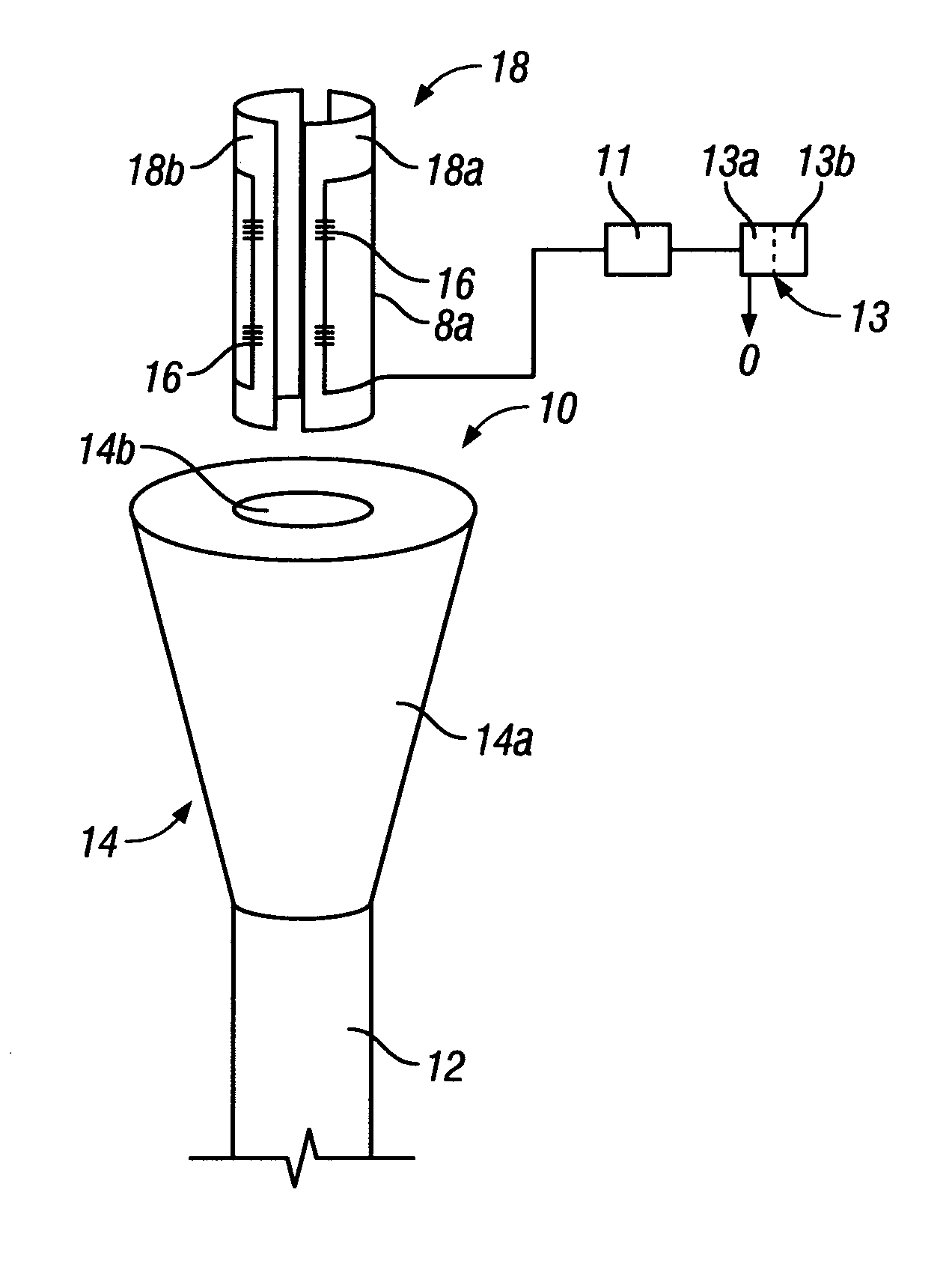
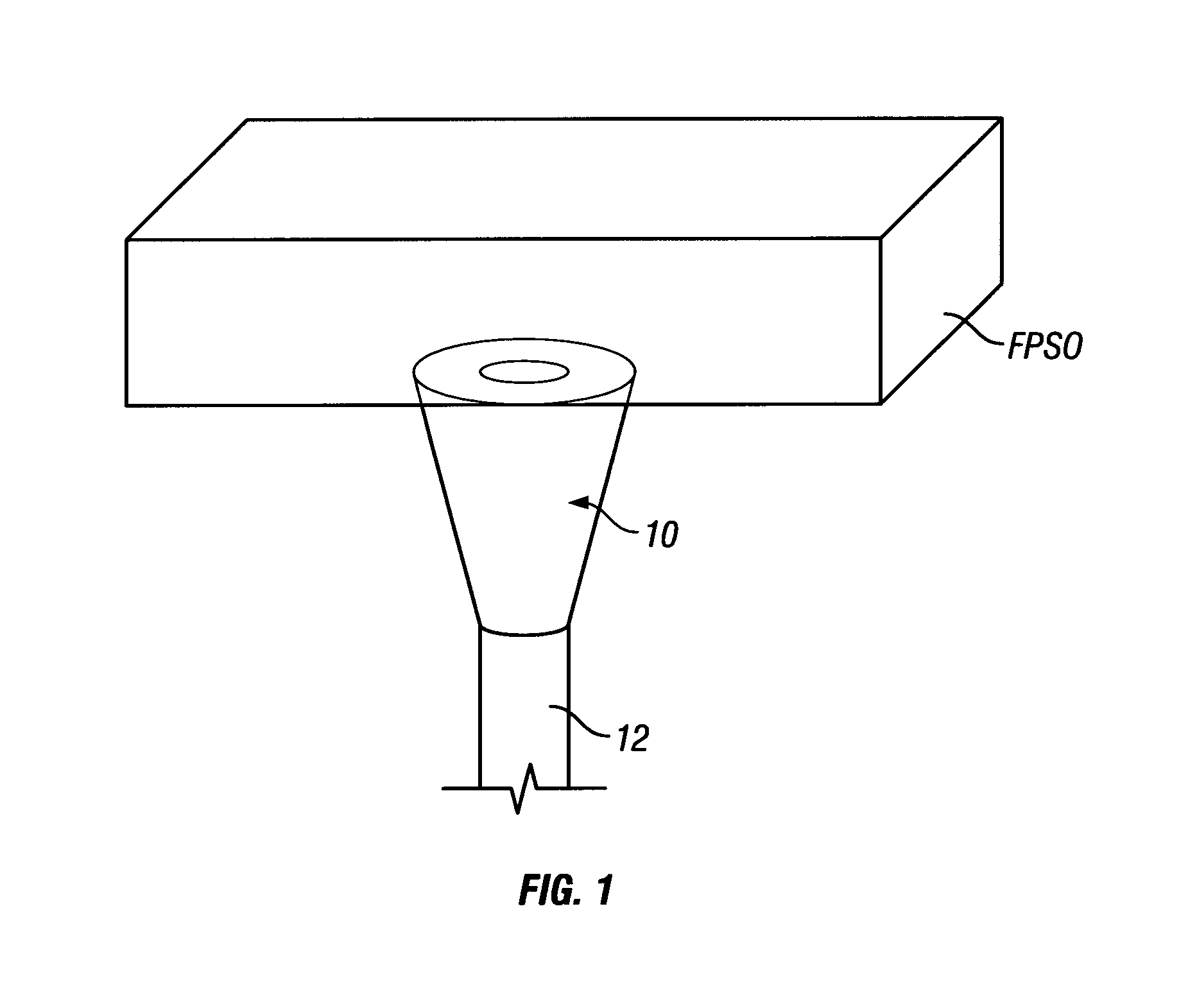
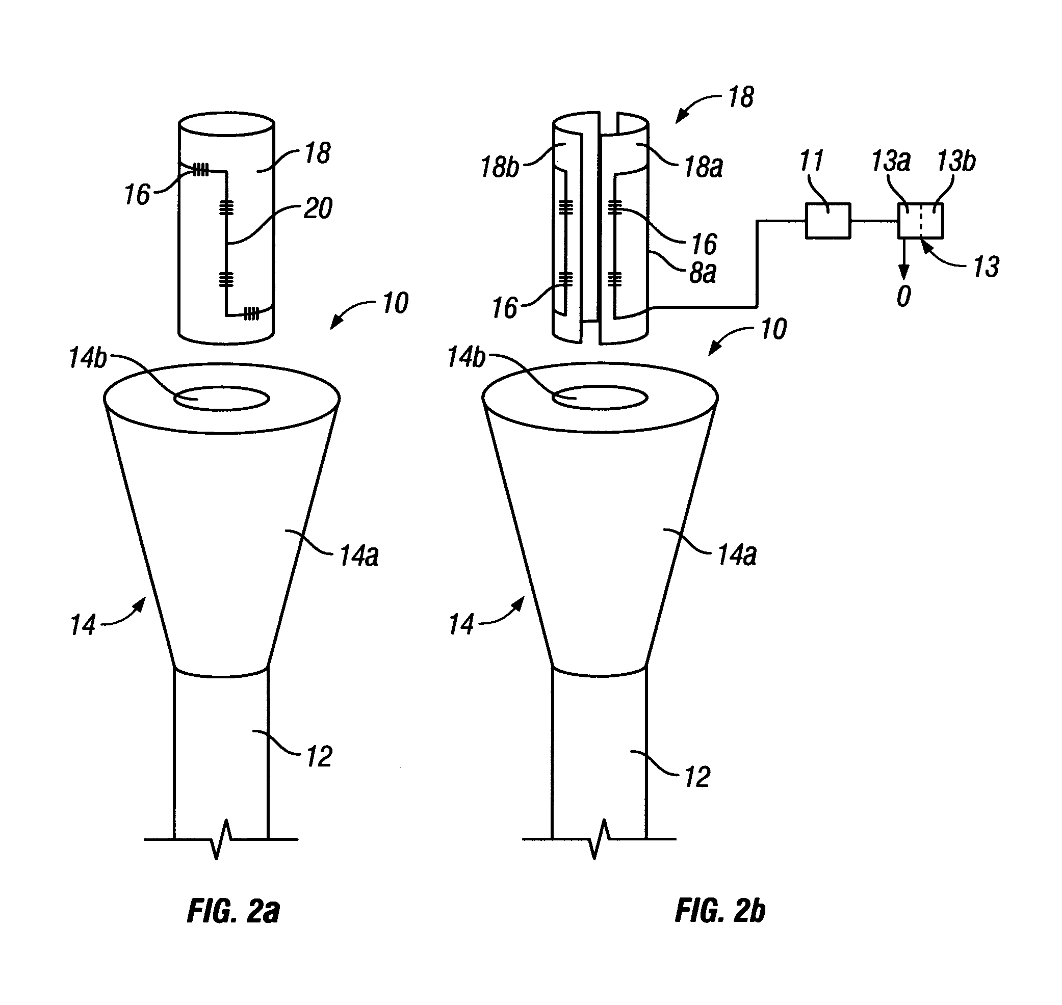
[0042]the invention provides a terminal end-attachment device 10 for a flexible pipe 12, as shown in FIGS. 1 and 2. In this example, the device 10 comprises a strain relief device for the terminal end of a sub-sea oil and / or gas production riser 12, the riser 12 being shown in FIG. 1 attached to a semi-fixed installation structure in the form of a floating production, storage and offload (FPSO) vessel. The terminal end-attachment device may alternatively comprise a bend stiffener or a termination device. The installation structure may alternatively comprise a platform, a manifold, a wellhead, a jumper or a buoy, and may be fixed or semi-fixed. e.g. floating.

[0043]The strain relief device 10 comprises an attachment body 14 and a plurality of strain sensors 16 coupled to a sensor carrier 18.

[0044]The attachment body 14 comprises generally inverted frusto-conical shaped body 14a and a central bore 14b. The attachment body 14 is adapted to receive a terminal end of the production riser ...

second embodiment

[0050]Referring to FIGS. 3 and 4, the invention provides a method 30 of manufacturing a terminal end-attachment device for a flexible pipe. In this example the terminal end-attachment device comprises a strain relief device 10 of the type shown in FIG. 2a and the same reference numbers are retained for corresponding features.

[0051]The method 30 comprises forming a sensor carrier comprising a sensor carrier 18, such as a cylindrical shaped carrier member. The shaped carrier member comprises a mat of carbon fibre / epoxy resin composite which is formed into a cylindrical shape around former 42, as shown in FIG. 4a. A plurality of strain sensors, in the form of FBGs 16, are embedded into the shaped carrier member during formation of the shaped carrier member.

[0052]The attachment body 14 is formed within a moulding system 40 comprising an outer mould 44 and an inner mould, which in this example comprises the shaped carrier member. The shaped carrier member is provided within the outer mou...


PUM

PropertyMeasurementUnit
flexibleaaaaaaaaaa
buoyancyaaaaaaaaaa
structureaaaaaaaaaa

Abstract

A terminal end-attachment device (10) for a flexible pipe (12) comprising an attachment body (14) adapted to receive a terminal end of a flexible pipe (12) and to couple the said flexible pipe to a hydrocarbon production installation structure. The device (10) further comprising a strain sensor (16) coupled to a sensor carrier (18), at least part of the sensor carrier (18) and the strain sensor (16) being at least partially incorporated within the attachment body (14). A method of manufacturing a terminal end-attachment device (10) for a flexible pipe (12) is also provided.

Description

TECHNICAL FIELD[0001]The invention relates to a terminal end-attachment device for a flexible pipe, and particularly but not exclusively for a sub-sea oil and / or gas pipe, and to a method of manufacturing a terminal end-attachment device for a flexible pipe.BACKGROUND ART[0002]The monitoring of flexible pipes, such as production risers, jumpers and flowlines, in subsea hydrocarbon (oil and / or gas) production installations is necessary to avoid potentially catastrophic incidents like hydrocarbon spills, loss of well control and escape of gas, which can affect the buoyancy of floating production, storage and offload (FPSO) vessels. Several techniques to identify damage in flexible pipes have been proposed, as reported in the UKOOA document “Guidance notes on monitoring method and integrity assurance for unbonded flexible pipe”. The techniques commonly used in the offshore oil and gas industry are time consuming and require the production of hydrocarbons to be partially or completely s...

Claims


Application Information

Patent Timeline
Patent Type & Authority Patents(United States)
IPC IPC(8): G01B7/16F16L33/28B29C70/70G01L3/04G01N3/08B29C70/72B67D9/02
CPCB67D9/02E21B17/017E21B43/013E21B47/0001F17D5/00G01L1/246B29C70/70B29C70/72F16L33/28G01B7/16E21B47/001
Inventor ROBERTS, DAMON RICHARDRAMOS, ROGERIO TADEUVANNUFFELEN, STEPHANE
Owner ONESUBSEA L L C
Why Eureka
Try Eureka