Guiding transmission shaft structure with cutting knife

A drive shaft, oriented technology, applied in ship propulsion, ship parts, ships, etc., can solve the problems of affecting the normal operation of the propeller, the ship loses power, damage the propeller, etc., and achieves ingenious structural design, flexible use and high cutting efficiency. Effect

Active Publication Date: 2019-01-11
东台市海一船用设备有限公司
View PDF6 Cites 4 Cited by
  • Summary
  • Abstract
  • Description
  • Claims
  • Application Information

AI Technical Summary

Problems solved by technology

[0002] As we all know, the propulsion device of a ship generally adopts the propeller method. The propeller is composed of a transmission shaft and a propeller blade. The propeller is connected to the output shaft of the power machine through the transmission shaft. There is a ship stern tube or a beauty frame at the connection of the propeller, and the drive shaft drives the propeller to rotate to drive the ship to sail. During navigation, the groove between the propeller drum and the ship stern tube or the beauty frame and the propeller drum is often covered by floating objects in the water. , fishing nets, cables, etc. are entangled, affecting the normal operation of the propeller, and sometimes causing damage to the propeller, loss of power of the ship, and major accidents

Method used


Image

  • Guiding transmission shaft structure with cutting knife
  • Guiding transmission shaft structure with cutting knife
  • Guiding transmission shaft structure with cutting knife

Examples


Embodiment Construction

[0017] The content of the present invention will be further described in detail below in conjunction with the accompanying drawings.

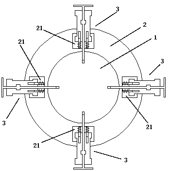
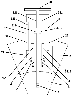
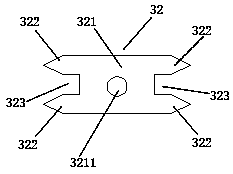
[0018] Such as Figures 1 to 4 As shown, a guide type transmission shaft structure with a cutter includes a transmission shaft 1, a connecting ring 2, a cutting mechanism 3, a guide column 4, and a guiding elastic body 5; the connecting ring 2 is fixedly sleeved on the transmission shaft 1 above; the outside of the connecting ring 2 is evenly provided with a plurality of installation grooves 21; the outside of the transmission shaft 1 is provided with a plurality of connecting threaded passages 11; the installation grooves around the outside of the connecting ring 2 21 corresponds to the position of the connecting threaded channel 11 around the outside of the transmission shaft 1; the mounting groove 21 and the connecting threaded channel 11 are communicated through the connecting groove; a cutting mechanism 3 is respectively installed in the d...


PUM


Abstract

The invention discloses a guiding type transmission shaft structure with a cutting knife, which comprises a transmission shaft, a connecting ring, a cutting mechanism, a guiding column and a guiding elastic body. The threading block of the invention realizes the stable guiding function by cooperating and plugging the guide hole and the guide column in the mounting groove, and sleeves the guide elastic body on the guide column, so that the whole cutting knife can more stably carry out the telescopic floating; and the cutting knife of the invention utilizes the driving screw to carry out telescopic floating in the mounting groove of the connecting ring, and adjusts the proper cutting depth. The cutting knife of the invention has ingenious structure design, and the front and back ends of thetwo sides of the connecting block are respectively provided with a blade, so that the double-edged cutting of the two sides is realized, and the cutting efficiency is high; at the same time, a clamping sliding groove is respectively arranged between the blades on both sides of the threading block, which is convenient for sliding connection between the threading block and the mounting groove, realizes telescopic floating adjustment, and is more flexible in use.

Description

technical field [0001] The invention relates to a guide type transmission shaft structure with a cutter. Background technique [0002] As we all know, the propulsion device of a ship generally adopts the propeller method. The propeller is composed of a transmission shaft and a propeller blade. The propeller is connected to the output shaft of the power machine through the transmission shaft. There is a ship stern tube or a beauty frame at the connection of the propeller, and the drive shaft drives the propeller to rotate to drive the ship to sail. During navigation, the groove between the propeller drum and the ship stern tube or the beauty frame and the propeller drum is often covered by floating objects in the water. , fishing nets, cables, etc. are entangled, affecting the normal operation of the propeller, and sometimes causing damage to the propeller, loss of power of the ship, and major accidents. Contents of the invention [0003] In view of the deficiencies of the...

Claims


Application Information

Patent Timeline
Patent Type & Authority Applications(China)
IPC IPC(8): B63H5/16
CPCB63H5/165
Inventor 徐小龙汪子昂王美兰
Owner 东台市海一船用设备有限公司
Why Eureka
Try Eureka