Supercharge Your Innovation With Domain-Expert AI Agents!

A wing installation and fixing mechanism

A fixed mechanism and wing technology, which is applied to self-propelled bombs, offensive equipment, projectiles, etc., can solve the problems of the thickness of the mounting seat, differences, and difficulty in ensuring assembly consistency, and achieves easy and quick disassembly and assembly, and aerodynamic performance. The effect of reducing and lowering the requirements for fit accuracy

Active Publication Date: 2020-10-16
JIANGXI HONGDU AVIATION IND GRP
View PDF4 Cites 0 Cited by
  • Summary
  • Abstract
  • Description
  • Claims
  • Application Information

AI Technical Summary

Problems solved by technology

However, in the existing structural design, most of them adopt the fixing method of the body mounting seat. Due to the need for fixing, the mounting seat is generally thicker than the wing itself, which is prone to the following problems in practical applications:
[0003] 1) Since most of the mounts are welded or bound, it is difficult to ensure the consistency of assembly;
[0004] 2) Generally, the installation seat adopts the connection form of the card notch. In order to play the role of lateral limit, the transition fit is generally used, and the processing accuracy of the installation seat and the wing is high;
[0005] 3) Since the processing accuracy and assembly accuracy of the mounting seat are difficult to guarantee a high level, it is easy to cause the actual performance to be inconsistent with the simulation performance, and there will be differences between individuals, which will cause certain difficulties in the design of the control system;
[0006] 4) The mounting seat exposes the surface of the missile body, forming multiple protrusions at the root of the wing, which has an extremely adverse effect on the aerodynamic performance of the wing and the entire missile, thereby restricting the relevant combat technical indicators of the missile

Method used


Image

  • A wing installation and fixing mechanism
  • A wing installation and fixing mechanism
  • A wing installation and fixing mechanism

Examples


Embodiment Construction

[0026] The present invention will be further described in detail below in conjunction with the accompanying drawings.

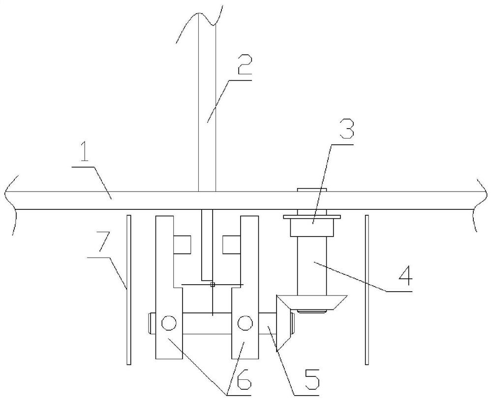
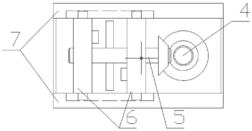
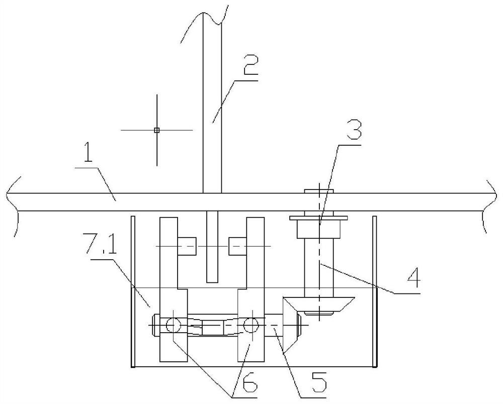
[0027] The invention mainly consists of two sets of helical gear transmission rods, a symmetrical clamping plate and a housing. One set of helical transmission rods passes through the skin and connects with the self-locking nut with self-locking function placed in the housing under the skin. Only the screw head with a "cross" groove is exposed outside the skin for operation. The symmetrical clamping plate is installed on the two sides of the shell through two hanging shafts. There are threaded holes with different rotation directions in the middle of the symmetrical clamping plate, which are connected with another set of helical gear transmission rods. The pinion gears are meshed, and the two transmission rods are in the form of a right angle. The casing connects each mechanism as a whole, and is fixed in the shell itself. There are grooves with guiding groo...


PUM


Abstract

The invention relates to a missile wing installing and fixing mechanism which comprises self-locking nuts (3), a longitudinal oblique tooth transmission rod (4), a transverse oblique tooth transmission rod (5), symmetrical clamping plates (6) and a shell (7). The longitudinal oblique tooth transmission rod (4) is inserted into a preset hole in skin (1). A gear of the bottom of the longitudinal oblique tooth transmission rod (4) is matched with a gear at one end of the transverse oblique tooth transmission rod (5). The transverse oblique tooth transmission rod (5) is screwed into thread holes of two symmetrical clamping plates (6). The missile wing installing and fixing mechanism is fixedly installed on the shell (7). According to the mechanism, the influence on aerodynamic performance is reduced greatly, missile wings are assembled and disassembled conveniently and rapidly, and for machining of the missile wing installing face, the requirement for matching precision is reduced greatly.

Description

technical field [0001] The invention belongs to the field of missile structure design, and relates to a missile wing installation and fixing mechanism, in particular to a missile wing installation and fixing mechanism with internal blind docking of missiles. Background technique [0002] The wing is the main provider of lift when the missile is in flight, and the conformal shape of the wing is the guarantee of the good aerodynamic performance of the missile. However, in the existing structural design, most of them adopt the fixing method of the body mounting seat. Due to the need for fixing, the mounting seat is generally thicker than the wing itself, which is prone to the following problems in practical applications: [0003] 1) Since most of the mounts are welded or bound, it is difficult to ensure the consistency of assembly; [0004] 2) Generally, the installation seat adopts the connection form of the card notch. In order to play the role of lateral limit, the transiti...

Claims


Application Information

Patent Timeline
Patent Type & Authority Patents(China)
IPC IPC(8): F42B10/04F42B15/00
CPCF42B10/04F42B15/00
Inventor 罗敏芳张鹏高辉王刘星马庆跃冯伦天王克强张维
Owner JIANGXI HONGDU AVIATION IND GRP
Features
  • R&D
  • Intellectual Property
  • Life Sciences
  • Materials
  • Tech Scout
  • Unparalleled Data Quality
  • Higher Quality Content
  • 60% Fewer Hallucinations
Learn More