Circuit structure for realizing fault emergency replacement function of power amplification link

A technology for power amplification and link failure, applied in radio wave measurement systems, instruments, etc., to ensure stability, avoid the loss of key signals in the system, and avoid missing effects

Active Publication Date: 2019-01-11
CNGC INST NO 206 OF CHINA ARMS IND GRP
View PDF7 Cites 1 Cited by
  • Summary
  • Abstract
  • Description
  • Claims
  • Application Information

AI Technical Summary

Problems solved by technology

[0004] The invention proposes a circuit composition form that can realize the emergency replacement function of radar key signal amplification link failure, and focuses on solving the problem that in the application of large-scale phased array radar, when individual key component hardware fails, the system can quickly realize the backup hardware The problem of automatic switching and turning on work

Method used


Image

  • Circuit structure for realizing fault emergency replacement function of power amplification link

Examples


Embodiment Construction

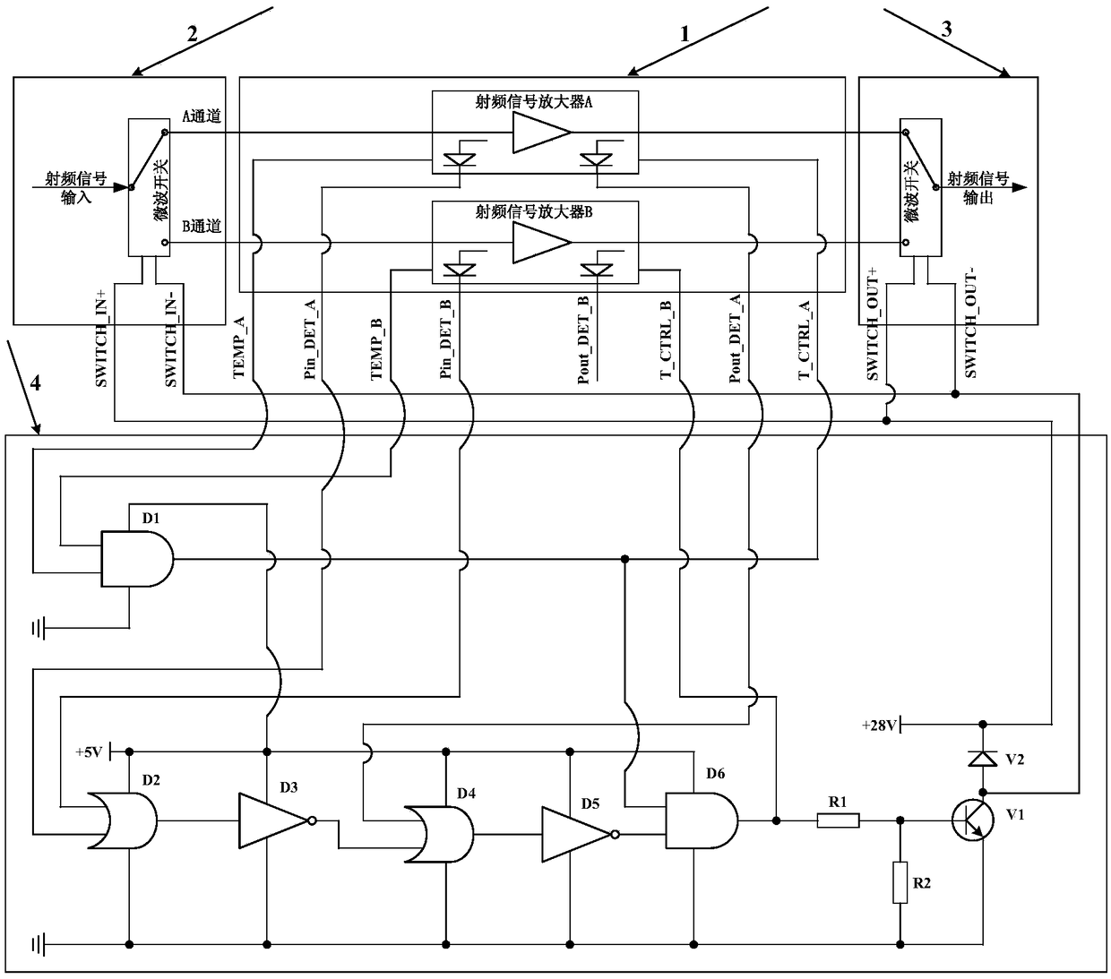
[0012] Now in conjunction with embodiment, accompanying drawing, the present invention will be further described:

[0013] In the radar system, the power amplification of key signals such as clock, synchronization, and local oscillator is generally realized by a centralized power amplifier, and the amplified power is transmitted to each transceiver sub-array or transceiver channel through a power distribution network. Once a single centralized power amplification link fails during use, it will inevitably lead to the loss of key system signals and cause the radar to malfunction. In the present invention, we propose a new circuit composition form by adding a spare amplifier combined with the corresponding logic control circuit, which can effectively avoid the aforementioned problems. The specific technical solution is: the fault emergency replacement circuit is composed of two power amplifiers, the main selection and the backup, two single-pole double-throw switches for input an...


PUM


Abstract

The invention provides a circuit structure for realizing a fault emergency replacement function of a power amplification link. The invention realizes the emergency replacement function that a main amplifier instantaneously and automatically switches to a spare amplifier and starts the operation, which is in the event of a failure, to ensure a normal operation of a system key signal power amplification link, and maintain the stability of the phased array radar state by the method of adding a spare power amplifier B on the basis of a system key signal main power amplifier A , combining an application of input and output single-pole double-throw switches, and setting control circuit judgment logic reasonably.

Description

technical field [0001] The invention can be applied to the technical field of radar, especially large-scale phased array radar, and specifically proposes a circuit composition form for realizing the emergency replacement function of a power amplification link failure. The reliability and stability of the power amplification link of key signals (such as system clock signals, synchronization signals, local oscillator signals, etc.). Background technique [0002] With the rapid development of radar technology, large-scale phased array radar has become the current mainstream development trend. Under this new radar system, the transmission and reception of radio frequency and microwave signals used for target detection and identification are mostly completed through a large number of transceiver components. The system design fully considers the tolerance of hardware failures. When a certain number of transceiver components within a certain proportion fail, the radar system can s...

Claims


Application Information

Patent Timeline
Patent Type & Authority Applications(China)
IPC IPC(8): G01S7/02
CPCG01S7/02
Inventor 周海进雷国忠康颖王嘉煜李磊
Owner CNGC INST NO 206 OF CHINA ARMS IND GRP
Why Eureka
Try Eureka