A splicing assembly and a lamp

A technology of components and lamps, which is applied in the direction of contact parts, parts of connecting devices, devices for connecting/disconnecting parts, etc., can solve the problems of no fixed positioning, complicated line layout, poor uniformity, etc., and achieve strong practicability , strengthen splicing, and reduce production costs

Pending Publication Date: 2019-01-11
范丰源
View PDF0 Cites 3 Cited by
  • Summary
  • Abstract
  • Description
  • Claims
  • Application Information

AI Technical Summary

Problems solved by technology

[0003] First, the lamps are suspended from the ceiling with steel wires, and there is no fixed positioning between two adjacent lamps, and the uniformity is poor;
[0004] Second, multiple lamps combined together need to be installed with a corresponding number of power lines hanging from the ceiling. The line layout is too complicated and the cost is high.

Method used


Image

  • A splicing assembly and a lamp
  • A splicing assembly and a lamp
  • A splicing assembly and a lamp

Examples


Embodiment Construction

[0028] In order to make the purpose, technical solutions and advantages of the embodiments of the present invention clearer, the technical solutions in the embodiments of the present invention will be clearly and completely described below in conjunction with the drawings in the embodiments of the present invention. Obviously, the described embodiments It is a part of embodiments of the present invention, but not all embodiments. The components of the embodiments of the invention generally described and illustrated in the figures herein may be arranged and designed in a variety of different configurations. Accordingly, the following detailed description of the embodiments of the invention provided in the accompanying drawings is not intended to limit the scope of the claimed invention, but merely represents selected embodiments of the invention.

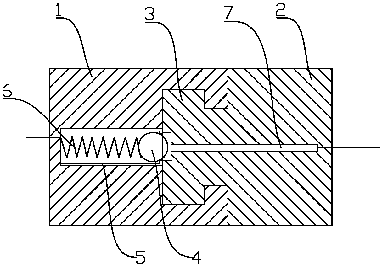
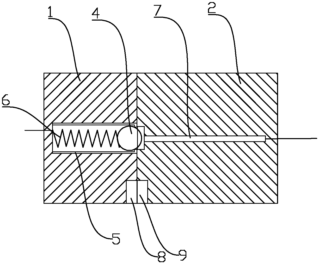
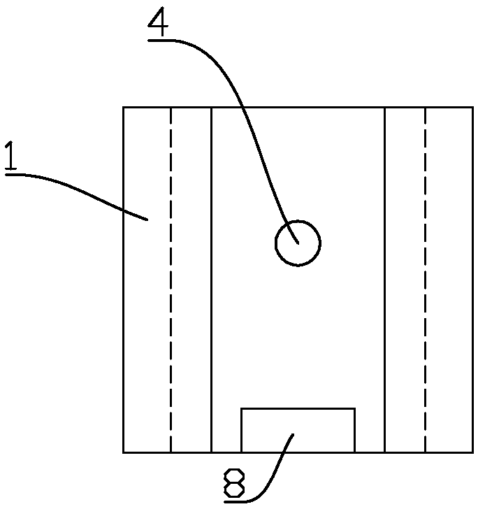
[0029] refer to Figure 1 to Figure 8 , this embodiment discloses a splicing assembly, which includes:

[0030] The male connecto...


PUM


Abstract

The invention discloses a splicing assembly and a lamp. The lamp is applied with the splicing assembly. The splicing assembly specifically comprises a male connector, one end of which is provided witha slot, and one side wall of the slot is provided with an opening to form a T-shaped channel. The female connector has a fastening portion adapted to the slot and can be mounted on the male connectorby pushing the fastening portion into the slot from the end of the slot. Thus, two adjacent lamps which need to be stitched together can be securely stitched together through a male connector and a female connector; When the lamps are spliced together, the electric circuit is serially connected by the press-in type electric connector and the electric connector, and the power supply wires are onlyarranged at two ends of the spliced lamps, and the lamps located in the middle do not need to be separately arranged with the power supply wires, thus simplifying the arrangement of the electric wires, reducing the production cost, and having strong practicability.

Description

technical field [0001] The invention belongs to the technical field of lamps, and in particular relates to a splicing component for realizing splicing of lamps and a lamp using the splicing component. Background technique [0002] In some application scenarios, more lighting fixtures need to be installed, and the lighting fixtures need to be combined together. However, the traditional lamps have the following deficiencies in the actual splicing process: [0003] First, the lamps are suspended from the ceiling with steel wires, and there is no fixed positioning between two adjacent lamps, and the uniformity is poor; [0004] Second, a plurality of light fixtures assembled together need to be provided with a corresponding number of power lines hanging from the ceiling. The line layout is too complicated and the cost is high. Contents of the invention [0005] In order to solve the above problems, the present invention provides a splicing assembly that can be installed at t...

Claims


Application Information

Patent Timeline
Patent Type & Authority Applications(China)
IPC IPC(8): H01R13/02H01R13/24H01R13/46H01R13/62H01R24/00H01R35/00F21V23/06F21V21/002
CPCH01R13/02F21V21/002F21V23/06H01R13/2421H01R13/2478H01R13/46H01R13/6205H01R24/00H01R35/00
Inventor 范丰源
Owner 范丰源
Why Eureka
Try Eureka