Eureka AIR delivers breakthrough ideas for toughest innovation challenges, trusted by R&D personnel around the world.

Reinforcement butt welding machine for construction

A technology for building construction and butt welding machines. It is applied in the direction of manufacturing tools, welding equipment, auxiliary welding equipment, etc. It can solve the problems of low applicability, contact error, and inability to ensure the bonding of welding surfaces, etc., and achieve precise adjustment and avoid bending. Effect

Active Publication Date: 2019-12-17
湖北富华建筑安装有限公司
View PDF10 Cites 4 Cited by
  • Summary
  • Abstract
  • Description
  • Claims
  • Application Information

AI Technical Summary

Problems solved by technology

[0003] Chinese patent authorization announcement number CN206343832U proposes a self-rotating steel bar butt welding equipment, which rotates the steel bar so that the welding part can get a comprehensive welding effect, but the applicability is low, mainly because the welding surface cannot be guaranteed to be perfect during the butt joint process The existing method mainly relies on manual adjustment before welding, and realizes the butt joint of steel bars based on experience. It is easy to produce contact errors during the welding process, resulting in weak welding.

Method used


Image

  • Reinforcement butt welding machine for construction
  • Reinforcement butt welding machine for construction
  • Reinforcement butt welding machine for construction

Examples


Embodiment 1

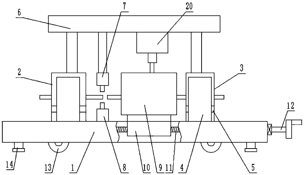
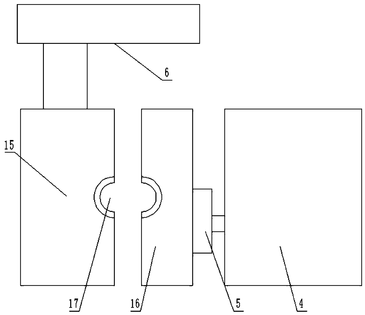
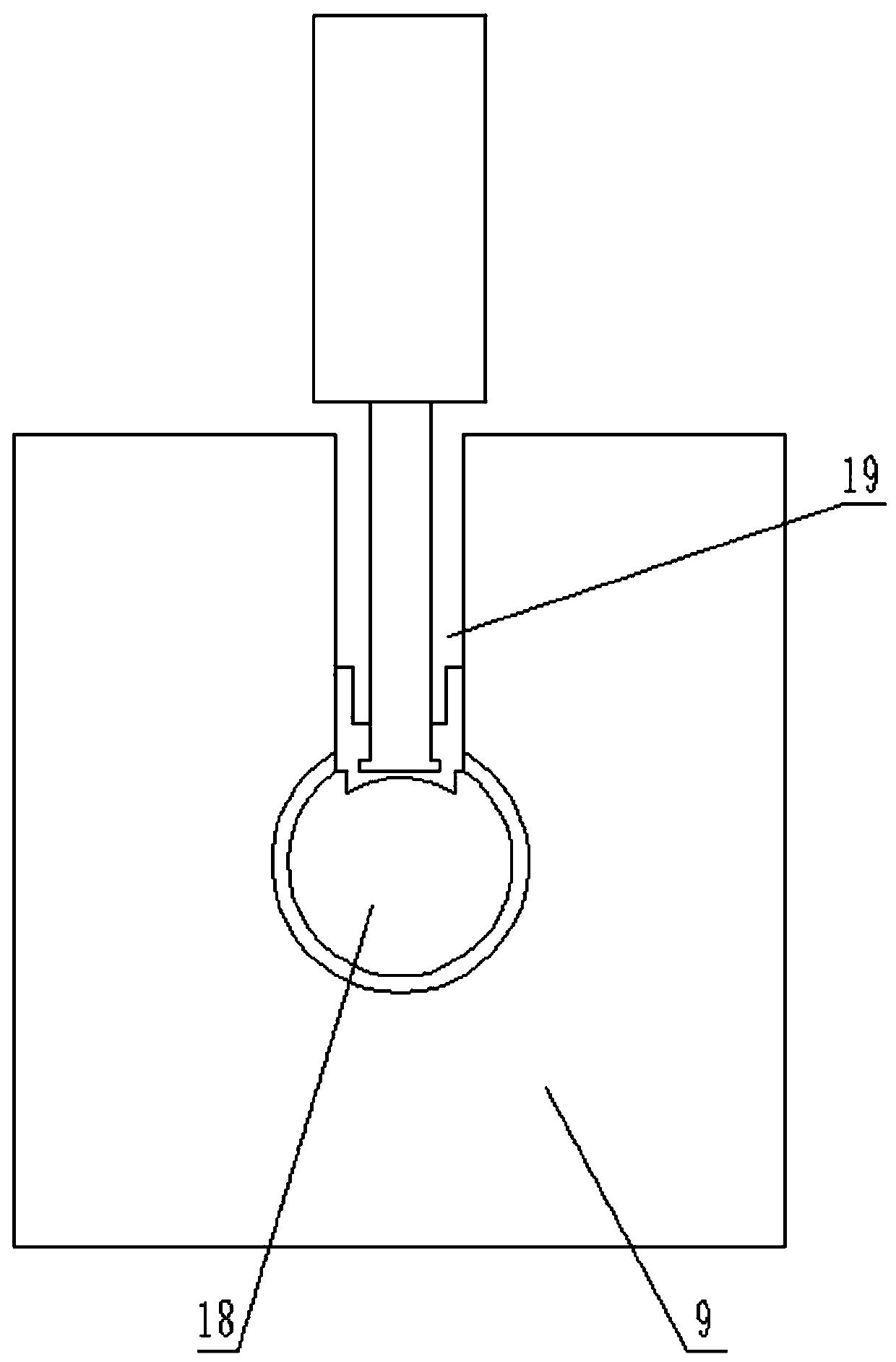
[0020] see Figure 1-4 , a steel bar butt welding machine for building construction, comprising an equipment frame 1, a wheel 13 is provided at the bottom of the equipment frame 1, a front fixer 2 and a rear fixer 3 are arranged on the top surface of the equipment frame 1, and the front fixer 2 and the rear fixer Device 3 is respectively used for fixing two steel bars to be welded, and is convenient to carry out welding work, is provided with upper welding gun 7 and lower welding gun 8 between front fixer 2 and rear fixer 3, upper welding gun 7 and lower welding gun 8 are arranged symmetrically, the lower welding gun 8 is fixed on the top surface of the equipment frame 1, the upper welding gun 7 is fixed on the bottom of the top frame 6, and the two sides of the top frame 6 are fixed on the top surfaces of the front holder 2 and the rear holder 3 through vertical rods Above, a movable fixer 9 is provided between the front fixer 2 and the rear fixer 3, and the movable fixer 9 i...

Embodiment 2

[0024] On the basis of Embodiment 1, in order to facilitate the mobile operation, the bottom of the equipment rack 1 is provided with a plurality of jacking screws 14, and the jacking screw rods 14 are threadedly connected with the equipment rack 1. When the equipment rack 1 is moved as a whole, The jacking screw 14 is rotated up, and after positioning, the jacking screw 14 is rotated down so that the bottom of the jacking screw 14 is grounded and the wheels 13 are separated from the ground, which is convenient for welding work at the construction site.


PUM


Abstract

The invention discloses a reinforcement butt welding machine for construction. The machine comprises an equipment frame; wheels are arranged at the bottom of the equipment frame; a front fixator and aback fixator are arranged on the top surface of the equipment frame; an upper welding gun and a lower welding gun are arranged between the front fixator and the back fixator, and are symmetrically arranged; the lower welding gun is fixed on the top surface of the equipment frame; the upper welding gun is fixed at the bottom of a top frame; the two sides of the top frame are fixed on the top surfaces of the front fixator and the back fixator through vertical rods; and a movable fixator is arranged between the front fixator and the back fixator. When the machine performs the positioning work, one reinforcement is firstly fixed through the front fixator, then, the other reinforcement is inserted in a ring groove in the movable fixator; a lifting rod is descended; after the reinforcements arefixed through a lifting slide block, the movable fixator moves to guarantee butt joint of the two reinforcements; and then, the reinforcements are fixed through the back fixator for welding, so thatthe adjustment is precise, and the reinforcements in butt joint are prevented from bending.

Description

technical field [0001] The invention relates to construction tools, in particular to a steel bar butt welding machine for construction. Background technique [0002] Butt welding of steel bars is a common processing method in the process of building construction. Mainly, two steel bars are welded together by flash welding or lap welding to achieve the required length. [0003] Chinese patent authorization announcement number CN206343832U proposes a self-rotating steel bar butt welding equipment, which rotates the steel bar so that the welding part can get a comprehensive welding effect, but the applicability is low, mainly because the welding surface cannot be guaranteed to be perfect during the butt joint process However, the existing method mainly relies on manual adjustment before welding and realizes the butt joint of steel bars based on experience. It is easy to produce contact errors during the welding process, resulting in weak welding. Contents of the invention ...

Claims


Application Information

Patent Timeline
Patent Type & Authority Applications(China)
IPC IPC(8): B23K37/04B21F15/08
CPCB21F15/08B23K37/0443
Inventor 蔡新新
Owner 湖北富华建筑安装有限公司
Why Eureka
Eureka Blog
Learn More