A high-power current stripping tool and its application method

A high-power, high-current technology, applied in the installation of cables, cable installation devices, electrical components, etc., can solve the problems of difficult removal of the enameled wire paint layer, low stripping efficiency, and increased staff fatigue, so as to reduce work. Quantity, novel design concept, fast and accurate peeling effect

Active Publication Date: 2020-04-03
WUXI JINGLEI ELECTRONICS
View PDF5 Cites 0 Cited by
  • Summary
  • Abstract
  • Description
  • Claims
  • Application Information

AI Technical Summary

Problems solved by technology

[0002] Stripping tooling is a tooling for separating the insulating layer on the surface of some wires. When producing high-power and high-current inductors, we will use some flat enameled wires. It is easy to wind, but this kind of enameled wire varnish It is difficult to remove the layer. With the progress and development of society, although all kinds of stripping tools appear in our lives, there are still some defects in the process of using them. Therefore, for a large Growing Demand for Power Current Stripping Tooling
[0003] At present, the partial stripping tooling in the field of stripping tooling is not very efficient in the process of stripping, and some stripping tooling can only be stripped of a single wire with human assistance. This stripping method is not only inefficient, but also increases the fatigue of the staff. In addition, it is easy to damage the wire body during the stripping work, and some stripping tools do not collect the stripped debris during use. If they are not collected centrally, it will lead to waste of resources and bring troubles to the follow-up cleaning work. Therefore, a high-power current stripping tool is proposed to solve the above problems

Method used


Image

  • A high-power current stripping tool and its application method
  • A high-power current stripping tool and its application method
  • A high-power current stripping tool and its application method

Examples


Embodiment Construction

[0027] The specific embodiments of the present invention will be described below in conjunction with the drawings.

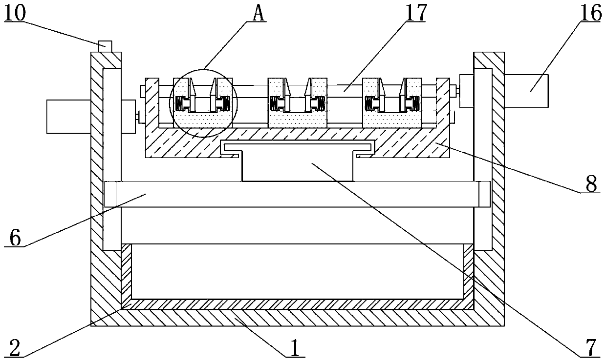
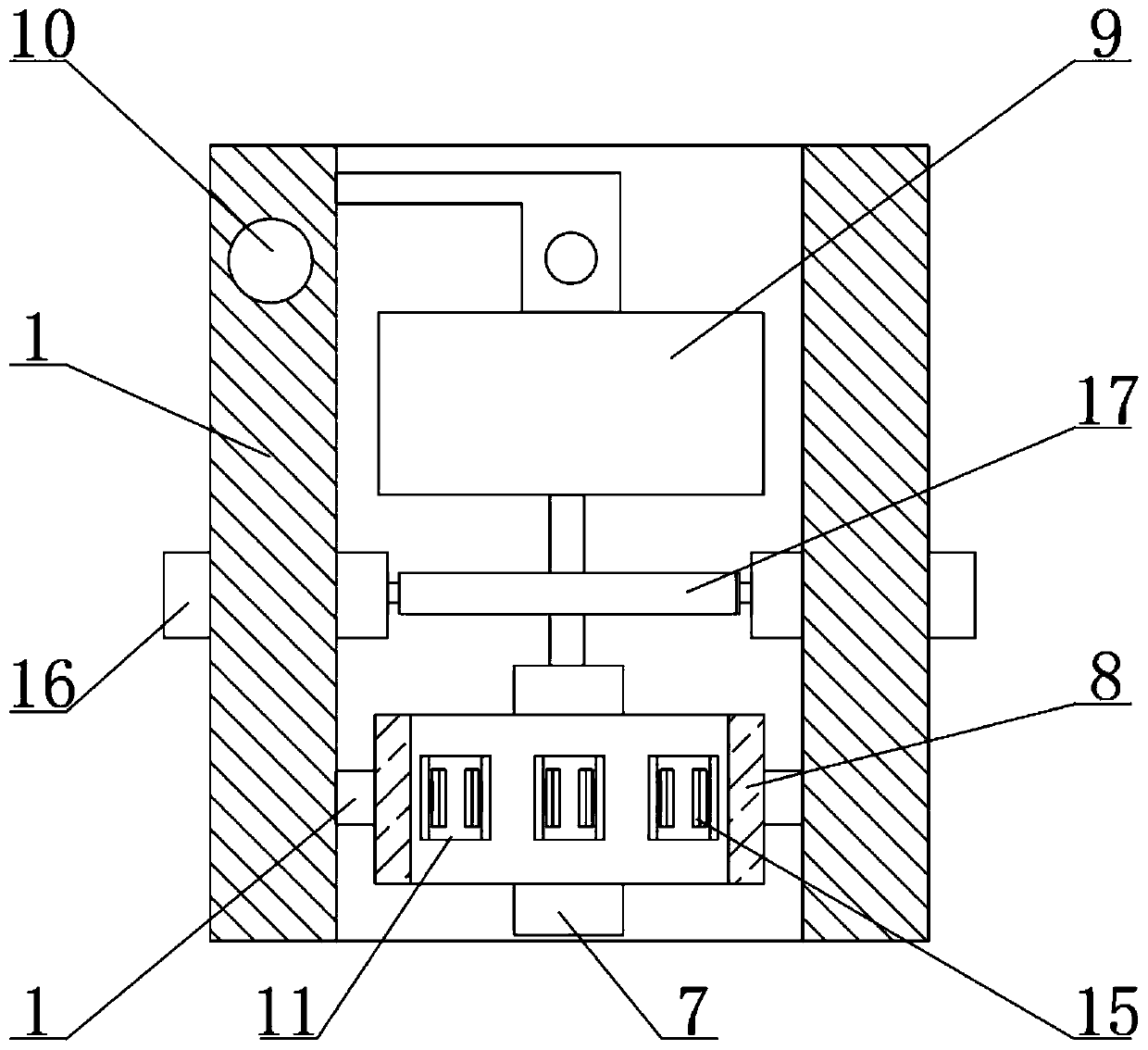
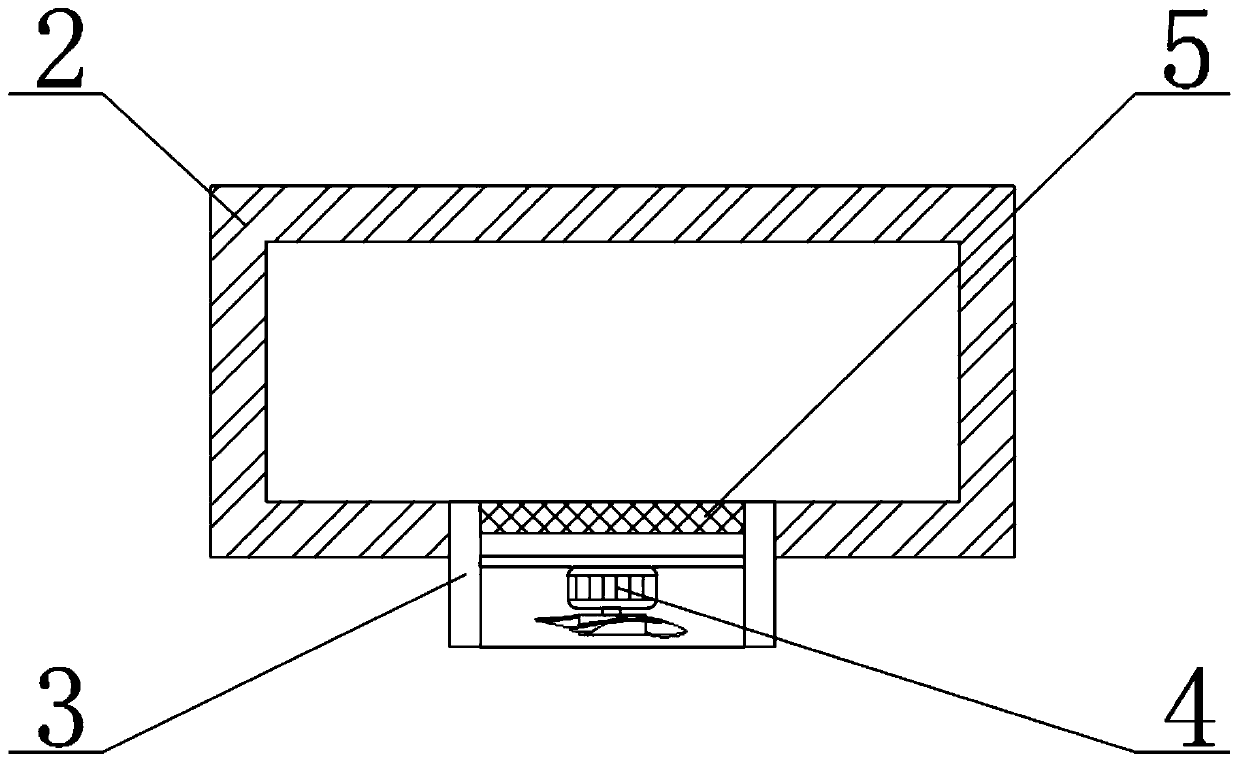
[0028] Such as figure 1 , figure 2 , image 3 with Figure 4 As shown, the high-power current stripping tooling of this embodiment includes a fixing frame 1 and a motor 16. A collection box 2 is slidably connected to the inner side of the bottom end of the fixing frame 1, and a wind box 3 is connected to the front end of the collection box 2. The fan 4 and the filter 5 are arranged front and rear, and the fan 4 is fixedly connected to the wind box 3 through a connecting rod, the filter 5 is fixedly connected to the wind box 3, the inner side of the fixing frame 1 is slidably connected with a sliding rod 6, and the top surface of the sliding rod 6 is fixedly connected with The first slider 7, the outer side of the first slider 7 is slidably connected to the limiter frame 8, the inner side of the fixed frame 1 is slidably connected to the peeling length positioning ...


PUM


Abstract

The invention relates to a high-power current stripping tooling and a use method thereof, including a mount and motor, a collection box is slidably connected to the inner side of the bottom end face of the fixing frame, a wind box is communicated with the front end surface of the collection box, a fan and a filter screen arranged in front and back are arranged on the inner side of the bellows, andthe fan is fixedly connected with the bellows through a connecting rod, the filter screen is fixedly connected with the bellows, a slide bar is slidably connected to the inside of the fixing frame, afirst slider is fixedly connected to the top end surface of the slide bar, a limit frame is slidably connected to that out side of the first slider, a location block with a stripping length is slidably connected to that inner side of the fix frame through a connecting rod, In the invention, the collection box is arranged, and the arrangement cooperates with the storage function of the collectionbox and the wind guidance of the fan, so as to collect the stripped debris centrally to the maximum extent, thus avoiding the waste of resources and lightening the workload of the cleaning work of thesubsequent tooling.

Description

Technical field [0001] The invention relates to the technical field of stripping tooling, in particular to a high-power current stripping tooling and a use method thereof. Background technique [0002] Stripping tooling is a tool for separating the insulating layer on the surface of some wires. When producing high-power and high-current inductors, we will use some flat enameled wires, which are convenient to wind, but this type of enameled wire is enameled The layer is difficult to remove. With the progress and development of society, although all kinds of stripped tooling appear in our lives, there are still some defects in the stripped tooling during the use process. Therefore, there is a large The demand for power current stripping tooling is increasing. [0003] At present, the stripping efficiency of partial stripping tooling in the field of stripping tooling is not very high during use. The partial stripping tooling can only be stripped of a single wire with manual assistanc...

Claims


Application Information

Patent Timeline
Patent Type & Authority Patents(China)
IPC IPC(8): H02G1/12
CPCH02G1/1248
Inventor 刘宇蓝
Owner WUXI JINGLEI ELECTRONICS
Why Eureka
Try Eureka