
Battery charging device

A technology of battery charging and resistance, applied in the field of electronics, can solve problems such as acceleration, circuit damage and aging

Inactive Publication Date: 2019-01-11
HANGZHOU KUANFU TECH
View PDF0 Cites 0 Cited by
  • Summary
  • Abstract
  • Description
  • Claims
  • Application Information

AI Technical Summary

Problems solved by technology

[0002] During the charging process of the battery, overheating will damage the entire circuit or accelerate aging, so a battery charging device with overheating shutdown is designed for this purpose

Method used


Image

  • Battery charging device

Examples


Embodiment Construction

[0008] The content of the present invention will be further described below in conjunction with the accompanying drawings.

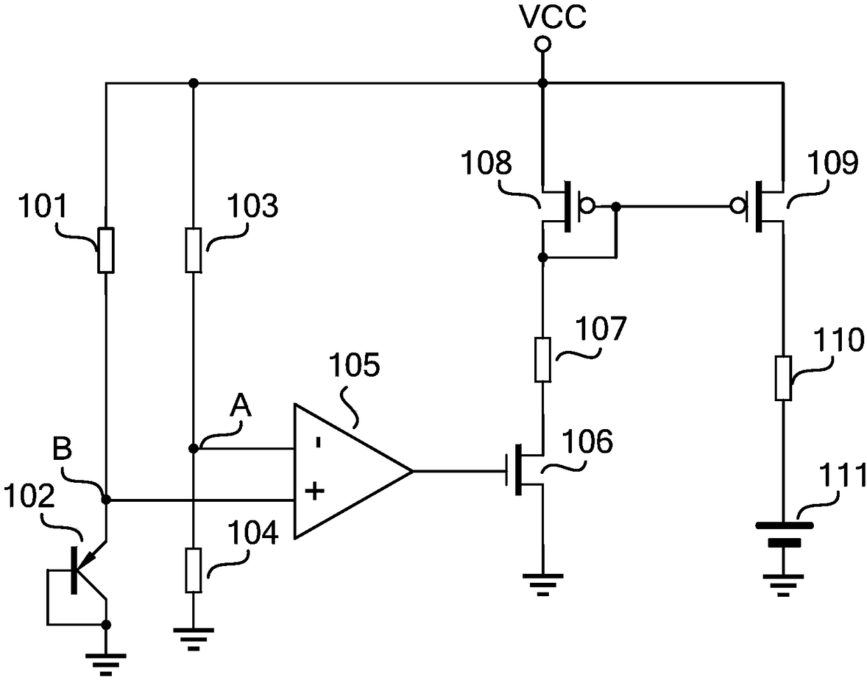
[0009] battery charging devices such as figure 1 As shown, it includes a first resistor 101, a first PNP transistor 102, a second resistor 103, a third resistor 104, a first comparator 105, a first NMOS transistor 106, a fourth resistor 107, a first PMOS transistor 108, a second PMOS tube 109, fifth resistor 110 and battery 111:

[0010] One end of the first resistor 101 is connected to the power supply voltage VCC, and the other end is connected to the emitter of the first PNP transistor 102 and the positive input of the first comparator 105; the base of the first PNP transistor 102 is grounded , the collector is grounded, the emitter is connected to one end of the first resistor 101 and the positive input end of the first comparator 105; one end of the second resistor 103 is connected to the power supply voltage VCC, and the other end is connected to ...


PUM


Abstract

The invention discloses a battery charging device. The battery charging device includes a first resistor, a first PNP tube, a second resistor, a third resistor, a first comparator, a first NMOS tube,a fourth resistor, a first PMOS tube, a second PMOS tube, a fifth resistor, and a battery. The battery charging device provided by the invention has the advantages of overheating shutdown and avoidingthe whole circuit damage or accelerated aging.

Description

technical field [0001] The invention relates to the field of electronic technology, in particular to a battery charging device. Background technique [0002] During battery charging, overheating will damage or accelerate the aging of the entire circuit, so a battery charging device with overheating shutdown is designed for this purpose. Contents of the invention [0003] The invention aims to solve the deficiencies of the prior art, and provides a battery charging device with overheating shutdown. [0004] The battery charging device includes a first resistor, a first PNP transistor, a second resistor, a third resistor, a first comparator, a first NMOS transistor, a fourth resistor, a first PMOS transistor, a second PMOS transistor, a fifth resistor and Battery: [0005] One end of the first resistor is connected to the power supply voltage VCC, and the other end is connected to the emitter of the first PNP transistor and the positive input end of the first comparator; t...

Claims


Application Information

Patent Timeline
Patent Type & Authority Applications(China)
IPC IPC(8): H02J7/00
CPCH02J7/0091H02J7/0086
Inventor 沈孙园
Owner HANGZHOU KUANFU TECH
Learn More