Formaldehyde adsorption machine

A formaldehyde adsorption and adsorption net technology, applied in the direction of gas treatment, membrane technology, dispersed particle separation, etc., can solve the problems of firm looseness, adsorption of large particles of dust and inconvenient cleaning, etc.

Inactive Publication Date: 2019-01-15
杭州棵林科技有限公司
View PDF0 Cites 4 Cited by
  • Summary
  • Abstract
  • Description
  • Claims
  • Application Information

AI Technical Summary

Problems solved by technology

[0004] The purpose of the present invention is to provide a formaldehyde adsorption machine to solve the problem that the vibration of the air purifier proposed

Method used


Image

  • Formaldehyde adsorption machine
  • Formaldehyde adsorption machine
  • Formaldehyde adsorption machine

Examples


Embodiment 1

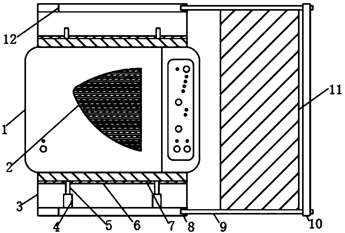
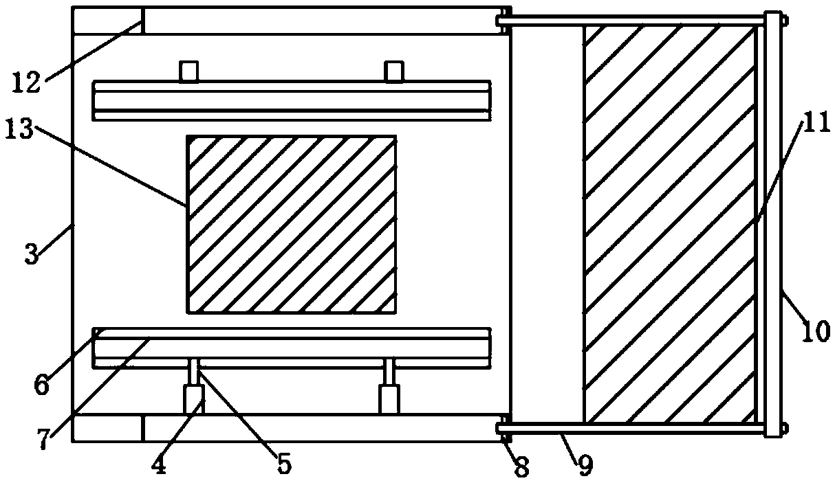
[0021] see figure 1 , figure 2 and image 3 , the present invention provides a technical solution: a formaldehyde adsorption machine, including a formaldehyde adsorption body 1, an adsorption net 2 and a fixed box 3, the adsorption net 2 is located in the middle of the surface of the formaldehyde adsorption body 1, and the formaldehyde adsorption body 1 is located in the middle of the fixed box 3, fixed The bottom surface of the box 3 is screwed and connected with four fixed columns 4, the top and bottom surfaces of the formaldehyde adsorption body 1 are respectively screwed and connected with the limiting plate 7, and the top of the fixed column 4 is provided with a movable column 5, And the top of moving column 5 is connected on the bottom surface of limit plate 7, and the surface of fixed box 3 top and bottom is symmetrically provided with moving bar 15, and one end of moving bar 15 is connected with moving plate 6 by screwing, and the fixed box 3 The four corners of the...

Embodiment 2

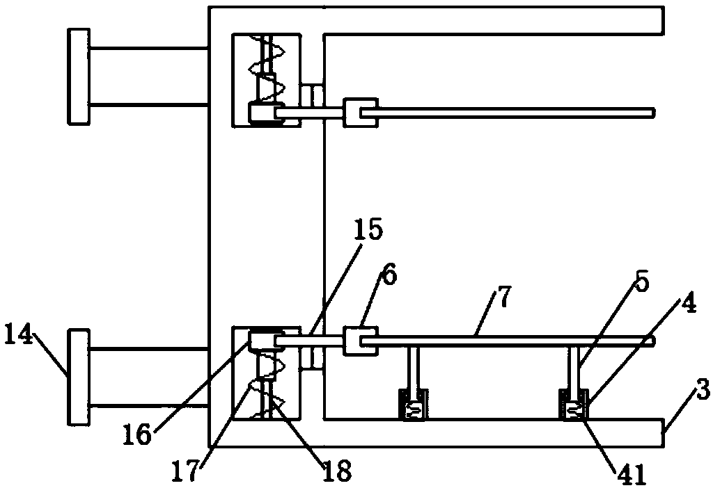
[0025] see figure 1 , figure 2 , image 3 , Figure 4 and Figure 5 , the present invention provides a technical solution: a formaldehyde adsorption machine, including a formaldehyde adsorption body 1, an adsorption net 2 and a fixed box 3, the adsorption net 2 is located in the middle of the surface of the formaldehyde adsorption body 1, and the formaldehyde adsorption body 1 is located in the middle of the fixed box 3, fixed The bottom surface of the box 3 is screwed with four fixed columns 4, and the interior of the fixed columns 4 is provided with a second spring 41, and the top and bottom surfaces of the formaldehyde adsorption body 1 are connected with the limiting plate 7 by screws. , the top of the fixed column 4 is provided with a moving column 5, and the top of the moving column 5 is connected to the bottom surface of the limit plate 7, the surface of the fixed box 3 top and the bottom are symmetrically provided with a moving bar 15, and one end of the moving bar...


PUM


Abstract

The invention discloses a formaldehyde adsorption machine, which includes a formaldehyde adsorption machine body, an adsorption screen and a fixing box. The adsorption screen is arranged on the centerposition of the surface of the formaldehyde adsorption machine body. The formaldehyde adsorption machine body is arranged in the middle of the fixing box. A plurality of fixing columns are disposed on the surface of the bottom end of the fixing box. Position limiting plates are respectively connected to the surfaces of the top end and bottom end of the formaldehyde adsorption machine body. A movable column is arranged on the top end of each fixing column. The top end of each movable column is connected to the bottom surface of each position limit plate. Movable rods are symmetrically arrangedon the surfaces of the top and bottom of the fixing box. A movable board is connected to one end of each movable rod. Connection columns are respectively arranged on the four corners of the rear endof the fixing box. A gauze screen sleeves the outer side of a connection rod, then a position limiting piece is clamped and connected to the connection rod and the connection rod is rotated, then a position limiting column is embedded in a round-shaped groove in the side surface of a fixed piece. The gauze screen can cover the surface of the adsorption screen, so that problems of instability due to vibration during use and inconvenience of cleaning large dust particles of an air purifier are avoided.

Description

technical field [0001] The invention belongs to the technical field of formaldehyde adsorption machines, in particular to formaldehyde adsorption machines. Background technique [0002] Air purifiers, also known as formaldehyde adsorption machines, refer to products that can absorb, decompose or transform formaldehyde and effectively improve air cleanliness. They are widely used in household, commercial, industrial, building, etc. There are many different technologies in air purifiers. and media, so that it can provide users with clean and safe air. Commonly used air purification technologies include adsorption technology, negative ion technology, catalytic technology, electrostatic dust collection technology, etc. The air purifier will produce weak vibrations during its operation. And it will be firm and loose for a long time, which will pose a safety hazard, and it will inevitably absorb large particles of dust during the process of adsorbing formaldehyde by the air purifi...

Claims


Application Information

Patent Timeline
IPC IPC(8): B01D53/04
CPCB01D53/04B01D53/0407B01D53/0438B01D2257/704B01D2257/708
Inventor 王朝
Owner 杭州棵林科技有限公司
Why Eureka
Try Eureka