A ceramic inner hole grinding machine
A technology of grinding machine and inner hole, which is applied in the direction of grinding machine parts, machine tools designed for grinding the rotating surface of workpieces, grinding drive devices, etc. The knife speed is increased, the effect is good, and the effect of improving the processing efficiency
- Summary
- Abstract
- Description
- Claims
- Application Information
AI Technical Summary
Problems solved by technology
Method used
Image

Examples
specific Embodiment approach 1
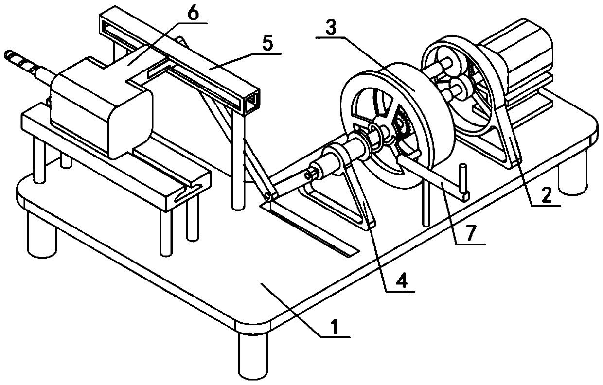
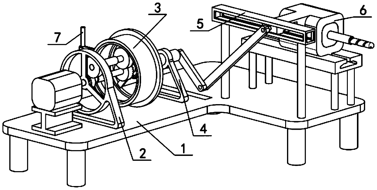
[0036] Combine below Figure 1-15 Description of this embodiment, a ceramic inner hole grinding machine, including a console 1, a speed change mechanism 2, a transmission mechanism 3, an input mechanism 4, an output mechanism 5, and an actuator 6, through which the speed change mechanism 2 makes the feed speed Slower, the effect of grinding the inner hole is better. Through the connecting rod Ⅰ5-1, connecting rod Ⅱ5-2, and slider 5-3, the speed of tool retraction is accelerated to improve processing efficiency, and it can speed up both the advance and retreat of the knife, and improve the reciprocating grinding of the inner hole. processing efficiency;
[0037] The console 1 includes a console main body 1-1, a motor base I1-2, a motor I1-3 and a port 1-4, the motor base I1-2 is fixedly connected to the console main body 1-1, and the motor I1 -3 is fixedly connected to the motor base Ⅰ1-2, and the port 1-4 is set on the console main body 1-1. The specific speed of the motor Ⅰ1...
specific Embodiment approach 2
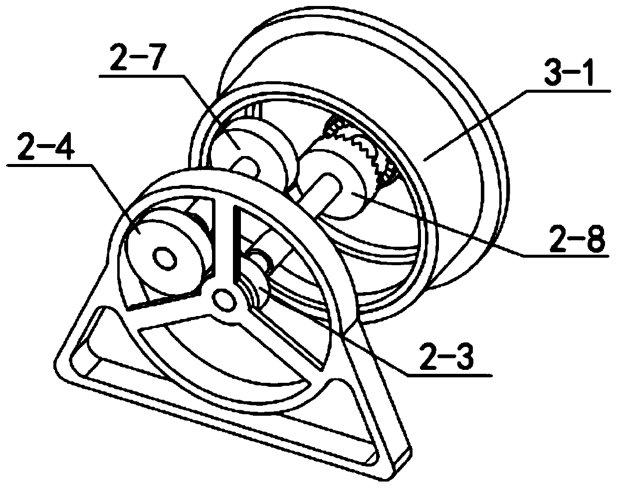
[0044] Combine below Figure 1-15 This embodiment will be described. This embodiment will further describe the first embodiment. The ceramic inner hole grinding machine also includes a brake member 7, and the brake member 7 includes a brake lever 7-1, a rotating shaft 7-2, Contact column 7-3 and handle 7-4, rotating shaft 7-2 are fixedly connected to the lower end of brake lever 7-1, contact column 7-3 is fixedly connected to the front side of brake lever 7-1 left end, handle 7-4 Fixedly connected to the upper side of the right end of the brake lever 7-1, the lower end of the rotating shaft 7-2 is rotatably connected to the console main body 1-1, and the contact post 7-3 contacts the rear end of the central wheel III 3-1.
specific Embodiment approach 3
[0046] Combine below Figure 1-15 This embodiment will be described. This embodiment will further describe the first embodiment. The motor I1-3 is a low-speed motor and has an electromagnetic brake.
PUM
 Abstract
Description
Claims
Application Information
 - R&D
- Intellectual Property
- Life Sciences
- Materials
- Tech Scout
- Unparalleled Data Quality
- Higher Quality Content
- 60% Fewer Hallucinations
Browse by: Latest US Patents, China's latest patents, Technical Efficacy Thesaurus, Application Domain, Technology Topic, Popular Technical Reports.
© 2025 PatSnap. All rights reserved.Legal|Privacy policy|Modern Slavery Act Transparency Statement|Sitemap|About US| Contact US: help@patsnap.com