
Plastic compression molding machine

A compression molding machine and plastic technology, applied in the field of plastic compression molding machines, can solve the problems of slow heating time, increased defective rate, rubber and plastic fragmentation, etc., to avoid excessively long or too short heating time, and reduce defective rate , the effect of increasing speed

Inactive Publication Date: 2019-01-15
芜湖凯兴汽车电子有限公司
View PDF3 Cites 0 Cited by
  • Summary
  • Abstract
  • Description
  • Claims
  • Application Information

AI Technical Summary

Problems solved by technology

[0002] With the continuous development of industry and the continuous change of people's needs, compression molding products are widely used. Compression molding is an important technology in plastic molding processing. It is widely used in industrial production and industrial processing. Rubber materials are used in closed The plastic processing method of forming products by means of heating and pressure in the mold cavity. Generally, when rubber is compressed and molded, the heating time is slow, and the heating time of rubber and plastic cannot be accurately controlled. If the heating time is too short, it will cause rubber and plastic. The brittleness is strong, and the rubber and plastic are prone to cracking during compression molding. If the heating time is too long, the rubber and plastic will be easily deformed, resulting in unqualified extruded plastic. If the rubber and plastic are compression molded, it will not be well Controlling the temperature will increase the rate of defective products and cause unnecessary losses

Method used


Image

  • Plastic compression molding machine

Examples


Embodiment Construction

[0012] In order to deepen the understanding of the present invention, the present invention will be further described below in conjunction with examples, which are only used to explain the present invention and do not constitute a limitation to the protection scope of the present invention.

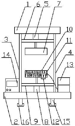
[0013] like figure 1 As shown, the present embodiment provides a plastic compression molding machine, including a top frame 1 and a base 2, a first frame 3 and a second frame 4 are symmetrically arranged between the top frame 1 and the base 2, and the The upper end of the upper part of the top frame 1 is provided with an upper die hydraulic cylinder 5, the lower part of the upper die hydraulic cylinder 5 is connected with an upper pressing plate 6, the lower part of the upper pressing plate 6 is provided with an upper pressing die 7, and the upper end of the middle part of the base 2 is provided with a The lower die hydraulic cylinder 8, the lower die hydraulic cylinder 8 is provided with...


PUM


Abstract

The invention provides a plastic compression molding machine. The machine comprises a top frame and a base, wherein a first rack and a second rack are symmetrically arranged between the top frame andthe base; an upper compression die hydraulic cylinder is arranged at the upper end of the middle part of the top frame, and an upper pressing plate is connected to the lower part of the upper compression die hydraulic cylinder; an upper compression die is arranged at the lower part of an upper compression plate; a lower compression die hydraulic cylinder is arranged at the upper end of the middlepart of the base, and a lower compression plate is arranged on the lower compression die hydraulic cylinder; a lower compression die is connected to the upper part of the lower compression plate, anda high-frequency induction coil is arranged in the lower compression die; a temperature sensor is arranged at the bottom part of the lower compression die; a high-frequency power supply is arranged atthe right side of the second rack; a PLC control end is arranged at the left side of the first rack; supporting feet are arranged below the base; the high-frequency induction coil is connected to thehigh-frequency power supply through a conductor; and the upper compression die hydraulic cylinder, the lower compression die hydraulic cylinder, the high-frequency power supply and the temperature sensor are electrically controlled to the PLC control end. According to the machine, the rubber plastic heating time can be accurately controlled, and excessive or insufficient heating time can be avoided, so that the defective percentage can be effectively reduced.

Description

technical field [0001] The invention relates to the field of plastic processing equipment, in particular to a plastic compression molding machine. Background technique [0002] With the continuous development of industry and the continuous change of people's needs, compression molding products are widely used. Compression molding is an important technology in plastic molding processing. It is widely used in industrial production and industrial processing. Rubber materials are used in closed The plastic processing method of forming products by means of heating and pressure in the mold cavity. Generally, when rubber is compressed and molded, the heating time is slow, and the heating time of rubber and plastic cannot be accurately controlled. If the heating time is too short, it will cause rubber and plastic. The brittleness is strong, and the rubber and plastic are prone to cracking during compression molding. If the heating time is too long, the rubber and plastic will be eas...

Claims


Application Information

Patent Timeline
Patent Type & Authority Applications(China)
IPC IPC(8): B29C43/02B29C43/52B29C43/58
CPCB29C43/02B29C43/52B29C43/58B29C2043/5816
Inventor 刘健
Owner 芜湖凯兴汽车电子有限公司
Learn More