Supercharge Your Innovation With Domain-Expert AI Agents!

pneumatic tire

A technology of pneumatic tires and tires, which is applied in the field of pneumatic tires and can solve problems such as wear and tear

Active Publication Date: 2022-06-07
SUMITOMO RUBBER IND LTD
View PDF19 Cites 0 Cited by
  • Summary
  • Abstract
  • Description
  • Claims
  • Application Information

AI Technical Summary

Problems solved by technology

Such a change in the shape of the ground contact surface has a problem of causing wear (partial wear) at a specific portion of the tread portion.

Method used


Image

  • pneumatic tire
  • pneumatic tire
  • pneumatic tire

Examples


Embodiment

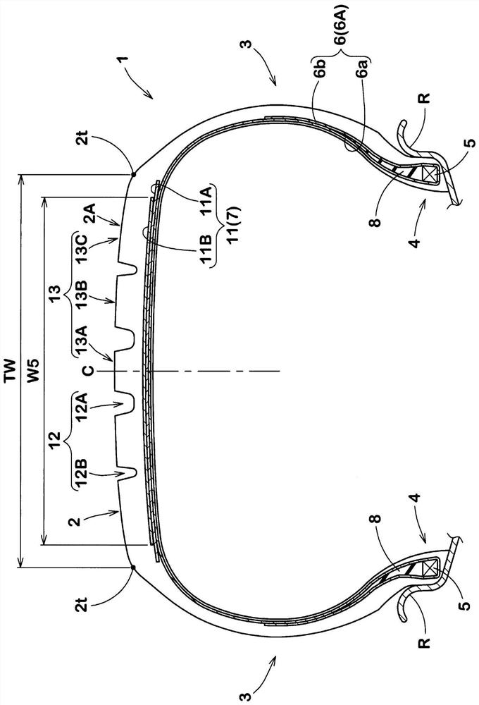
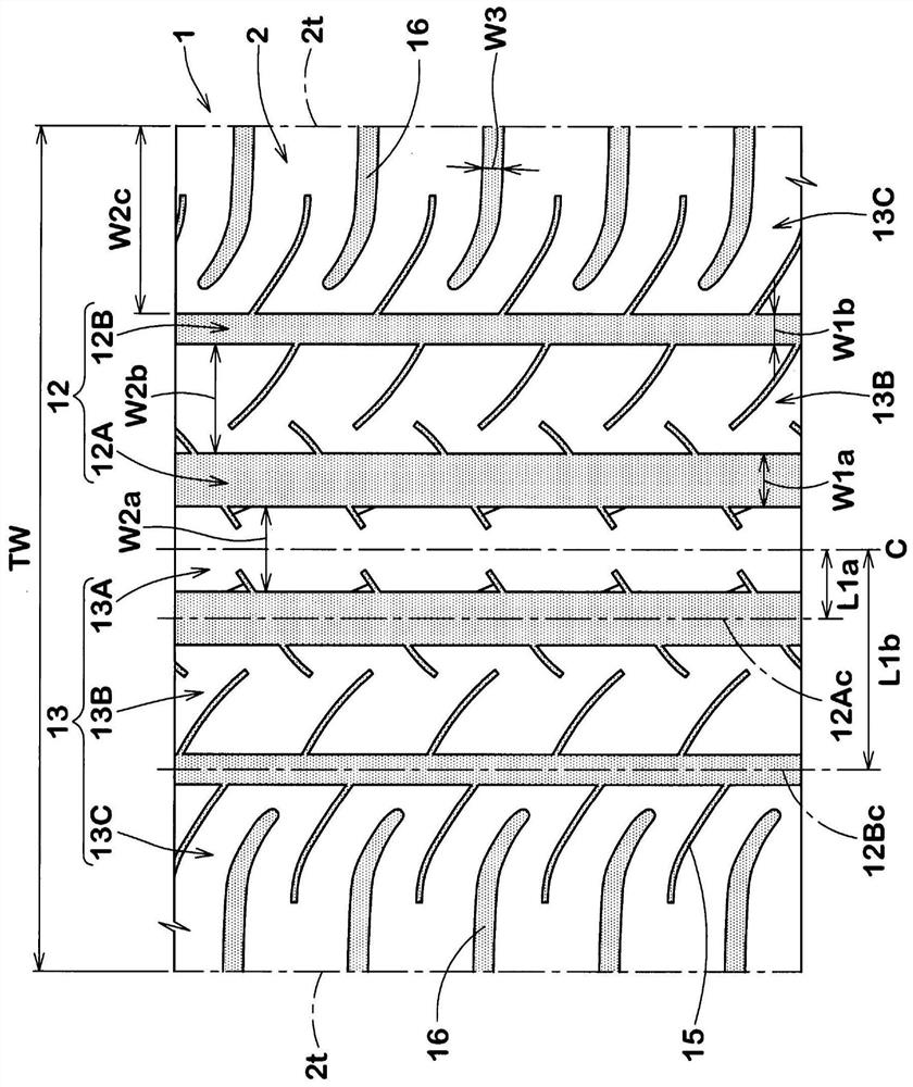
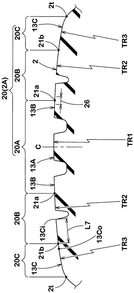
[0065] produced with figure 1 The basic structure shown in Table 1 shows the position of the maximum ground contact length portion, the outer belt ply and the profile of the tread portion (the first radius of curvature TR1, the second radius of curvature TR2, the Three tires with different curvature radii TR3) were used to evaluate their performance (Examples 1-8, Comparative Examples 1 and 2). The position of the part of the maximum ground length is in the grounded state with a camber angle of 3°, such as Figure 5 As shown, it is represented by the ratio L6 / Wm of the distance L6 from the central position of the contact patch to the side in the first direction in the tire axial direction to the maximum width Wm of the contact patch. The specifications common to each Example and Comparative Example are as follows.

[0066] Tire size: 195 / 65R15

[0067] Rim size: 15×6.0J

[0068] Internal pressure: 230kPa

[0069] Load: 4.22kN

[0070] Vehicle: Displacement 2000cm 3 Japa...


PUM


Abstract

The present invention provides a pneumatic tire capable of suppressing partial wear of a tread portion. This pneumatic tire has a tread portion (2). When the pneumatic tire is assembled on a standard rim with a standard internal pressure and is subjected to a standard load, it contacts the plane at a camber angle of 3° to the first direction (S1) at a camber angle of 3°. The ground surface (23) has a maximum ground contact length portion (24) having a maximum ground contact length (Lm) in the tire circumferential direction, and the maximum ground contact length portion (24) is located between the first direction (S1) side and A center position (25) of the contact patch (23) in the tire axial direction is separated by a distance (L6) of 20% to 30% of the maximum width (Wm) of the contact patch (23) in the tire axial direction.

Description

technical field [0001] The present invention relates to a pneumatic tire, and specifically, to a pneumatic tire capable of suppressing uneven wear of a tread portion. Background technique [0002] Generally, the ground contact surface of the tread portion of a pneumatic tire during straight travel has the largest ground contact length in the tire circumferential direction near the tire equator. On the other hand, when the tire is cornering, the portion of the contact surface of the tread portion having the largest contact length moves toward the tread end side on the outer side of the turn. Such a change in shape of the ground contact surface has a problem of causing wear (uneven wear) at a specific portion of the tread portion. [0003] Patent Document 1: Japanese Patent Laid-Open No. 2016-159788 Contents of the invention [0004] The present invention has been made in view of the above circumstances, and its main object is to provide a pneumatic tire capable of suppres...

Claims


Application Information

Patent Timeline
Patent Type & Authority Patents(China)
IPC IPC(8): B60C9/02B60C9/18
CPCB60C9/02B60C9/18B60C11/0083B60C11/1376B60C11/0332B60C11/04B60C11/1204B60C2011/0388B60C2011/039B60C2011/0341B60C2011/1209B60C2011/0358
Inventor 河津朱里
Owner SUMITOMO RUBBER IND LTD
Features
  • R&D
  • Intellectual Property
  • Life Sciences
  • Materials
  • Tech Scout
  • Unparalleled Data Quality
  • Higher Quality Content
  • 60% Fewer Hallucinations
Learn More