A trolley assembly and a track assembly for driving the movement of a turnout beam

A technology of turnout beams and rails, which is applied in the field of rail vehicles, and can solve problems such as heavy wear of trolley wheels and rails, derailment of trolleys, and difficult replacement, and achieve the effect of improving linearity and flexible lane change

Active Publication Date: 2021-04-20
BYD CO LTD
View PDF15 Cites 0 Cited by
  • Summary
  • Abstract
  • Description
  • Claims
  • Application Information

AI Technical Summary

Problems solved by technology

This technical solution has the following disadvantages: the four switch reducers are connected in series through the transmission shaft and the drum-shaped gear coupling, which requires high precision in the manufacture of the foundation and the bottom plate, and it is difficult to guarantee the installation accuracy of the entire mechanism; The bottom chute is driven by friction, with high vibration and noise, and the chute is easy to wear, and the chute is welded to the bottom of the turnout beam, so it is not easy to replace after wear; the driving device is installed on the ground foundation, which occupies a large area, which is not conducive to the safety of the turnout system
Due to problems such as manufacturing and installation accuracy and wear, the repeatability of the entire switch system is poor, and the system stability is not high; the structure is complex, the transmission ratio of the switch reducer is large, and the production cost is high
The beam-driven switch mechanism will cause the trolley to move in an arc-shaped trajectory, and the rails are also arc-shaped. The wheels of the trolley and the track slide relative to each other, resulting in low efficiency, heavy wear on the wheels and tracks of the trolley, difficulty in maintenance, and high maintenance costs; Difficult to manufacture, and the deviation of the movement line of the turnout will cause the risk of derailment of the trolley

Method used


Image

  • A trolley assembly and a track assembly for driving the movement of a turnout beam
  • A trolley assembly and a track assembly for driving the movement of a turnout beam
  • A trolley assembly and a track assembly for driving the movement of a turnout beam

Examples


Embodiment Construction

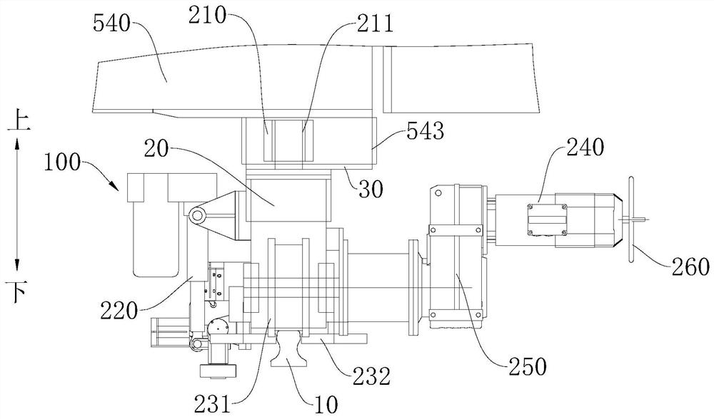
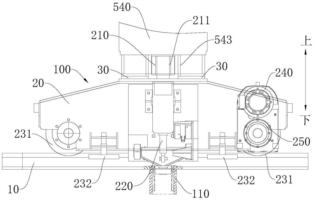
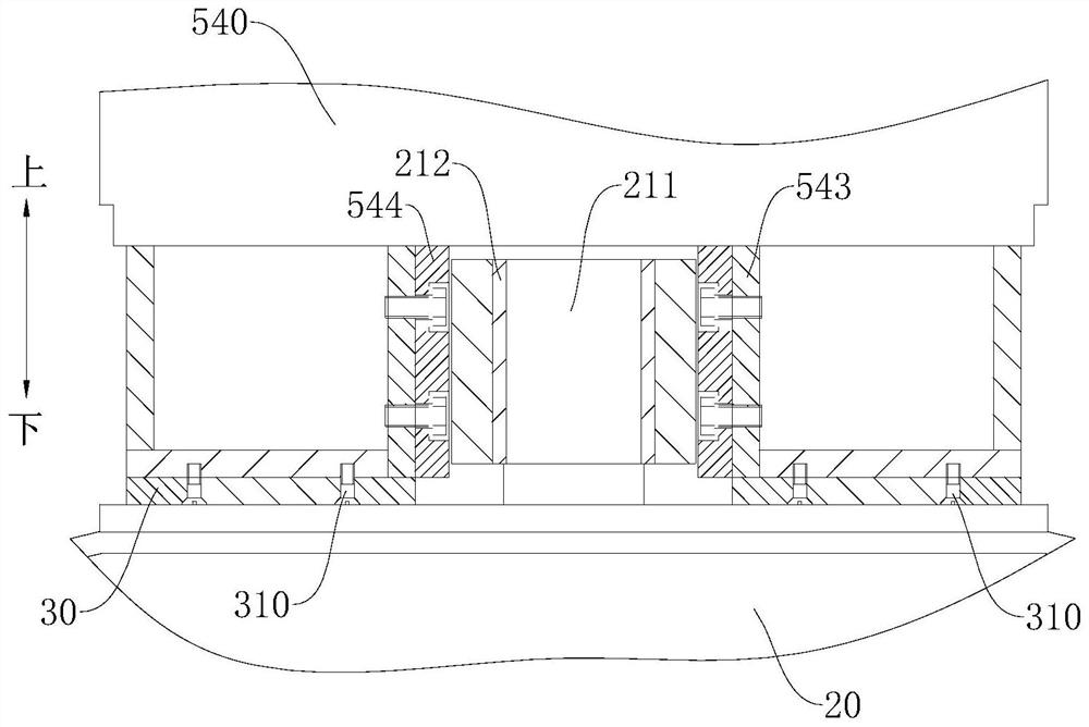
[0034] Embodiments of the present invention are described in detail below, examples of which are shown in the drawings, wherein the same or similar reference numerals designate the same or similar elements or elements having the same or similar functions throughout. The embodiments described below by referring to the figures are exemplary only for explaining the present invention and should not be construed as limiting the present invention.

[0035] In describing the present invention, it is to be understood that the terms "centre", "length", "upper", "lower", "front", "rear", "left", "right", "vertical", The orientation or positional relationship indicated by "horizontal", "top", "bottom", "inner", "outer", etc. is based on the orientation or positional relationship shown in the drawings, and is only for the convenience of describing the present invention and simplifying the description, and It is not to indicate or imply that the device or element referred to must have a pa...


PUM


Abstract

The invention discloses a trolley assembly for driving a switch beam to move. The switch beam has opposite first ends and a second end, the first end is fixed, the driving assembly is suitable for driving the second end to swing, and the switch beam has a chute , the chute extends along the length direction of the switch beam, the trolley assembly includes: a trolley track and a trolley body, and the trolley track extends along a straight line. The trolley body has a driving wheel, the driving wheel is rotatably located in the chute, and the trolley body is movably connected with the trolley track. According to the trolley assembly for driving the movement of the switch beam of the present invention, by arranging a chute extending along the length direction of the switch beam on the switch beam, a driving wheel is provided on the trolley assembly, and the driving wheel can roll in the chute, and The drive wheel can move along the extension direction of the chute. Therefore, through the mutual cooperation between the chute and the driving wheel, the switch beam can be driven to move by the trolley assembly, so as to adjust the position of the switch beam and realize the lane change of the rail vehicle.

Description

technical field [0001] The invention relates to the technical field of rail vehicles, in particular to a trolley assembly and a rail assembly for driving the movement of a turnout beam. Background technique [0002] The turnout beam can be adjusted to connect the track beams in different directions to realize the lane change of the rail vehicle, and the trolley is used to drive the movement of the turnout beam. In the related technology, the roller at the end of the turning arm of the trolley is driven by friction with the chute at the bottom of the turnout beam, and the four switch reducers are connected in series through the transmission shaft and the drum-shaped gear coupling. This technical solution has the following disadvantages: the four switch reducers are connected in series through the transmission shaft and the drum-shaped gear coupling, which requires high precision in the manufacture of the foundation and the bottom plate, and it is difficult to guarantee the in...

Claims


Application Information

Patent Timeline
Patent Type & Authority Patents(China)
IPC IPC(8): B61D15/00E01B7/10E01B2/00
CPCB61D15/00E01B2/00E01B7/10
Inventor 邓义昭陈柱何鹏
Owner BYD CO LTD
Why Eureka
Try Eureka