
A noise-reducing fan wind guide ring and a fan including the wind guide ring

An air guide ring and noise-reducing technology, which is applied in the field of noise-reducing fan air guide rings and fans including the air guide ring, can solve problems such as inability to achieve a good noise reduction effect, and achieve the goal of reducing middle and low frequency noise Effect

Active Publication Date: 2020-11-27
FANS TECH ELECTRIC CO LTD
View PDF1 Cites 0 Cited by
  • Summary
  • Abstract
  • Description
  • Claims
  • Application Information

AI Technical Summary

Problems solved by technology

This patent application forms a cavity between the wind guide ring body and the side plate for resonance and noise reduction, but since there is only one resonance cavity with a fixed volume, it cannot achieve a good noise reduction effect for noises with different frequency ranges

Method used


Image

  • A noise-reducing fan wind guide ring and a fan including the wind guide ring
  • A noise-reducing fan wind guide ring and a fan including the wind guide ring
  • A noise-reducing fan wind guide ring and a fan including the wind guide ring

Examples


Embodiment 2

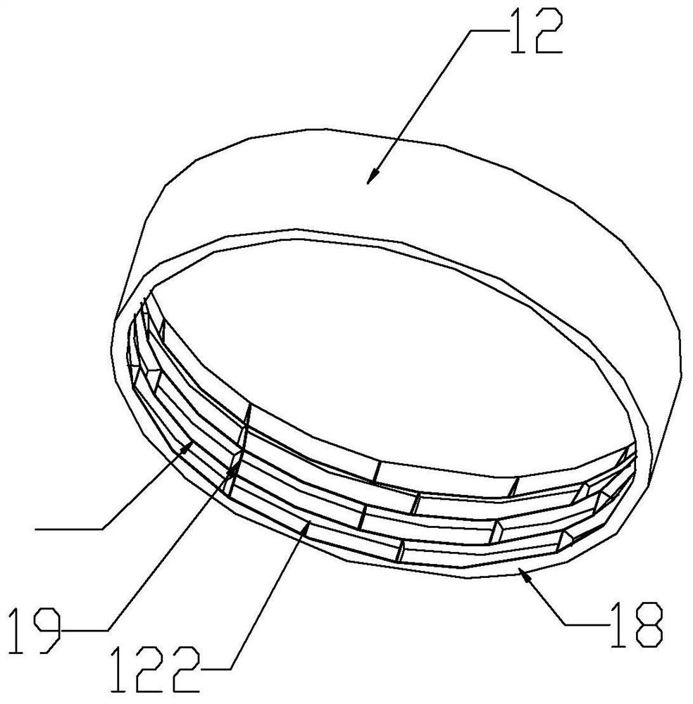
[0059] This embodiment only describes the difference from the above embodiment, and other technical features are the same as the above embodiment. In this embodiment, the distance between two adjacent risers 19 in each layer of the resonant cavity is arranged in a sequentially increasing or decreasing manner.

Embodiment 3

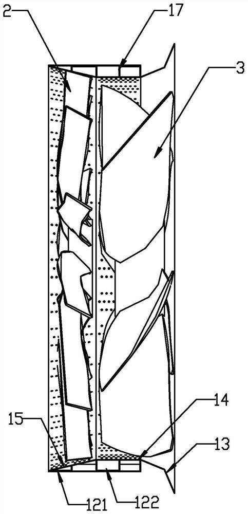
[0061] Such as figure 2As shown, this embodiment only describes the difference from the above embodiment, and the rest of the technical features are the same as the above embodiment. In this embodiment, the unit resonant cavity 122 is filled with sound-absorbing materials. The sound-absorbing material filled in the unit resonant cavity 122 can reduce the high-frequency noise in the fan 3. Since the wavelength of the high-frequency noise is relatively short, it cannot form reflection in the unit resonant cavity 122. Therefore, the unit resonant cavity 122 cannot prevent high-frequency noise. Noise reduction, but filling the unit resonant cavity 122 with sound-absorbing materials can effectively reduce high-frequency noise. The sound-absorbing material is one or more of inorganic fiber sound-absorbing materials, inorganic foam sound-absorbing materials, and foam plastic sound-absorbing materials. Preferably in this embodiment, the sound-absorbing material is one or more of me...

Embodiment 4

[0063] This embodiment only describes the difference from the above embodiment, and other technical features are the same as the above embodiment. In this embodiment, part of the unit resonant cavity 122 is filled with sound-absorbing material.


PUM


Abstract

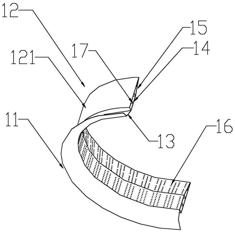
The invention discloses a noise-reduction-type fan air guide ring and a fan with the same. The fan comprises a blower, flow guide blades and the air guide ring; the air guide ring comprises an air guide ring side wall and a resonance cavity; the air guide ring side wall comprises a contraction section, a transition section and an expansion section; a plurality of micro through holes are designed in the inner surface of one side, close to the flow guide blades, of the air guide ring; the side wall of the resonance cavity is a closed surface; a resonance chamber is formed between the side wall surface of the air guide ring and the side wall of the resonance cavity; separation plates and vertical plates are arranged in the resonance cavity to form unit resonance cavities with different volumes; different resonance frequencies can be acquired based on different volumes of the unit resonance cavities; when frequency noises with similar resonance frequencies pass through holes in the surfaces of the unit resonance cavities, energy of the frequency noises can be reduced due to continuous reflection in the unit resonance cavities, and accordingly, low-and-medium-frequency noises are reduced; high-frequency noises can be effectively reduced through filling part of the unit resonance cavities with sound-absorbing materials.

Description

technical field [0001] The invention relates to the field of fans, in particular to a noise-reducing wind guide ring for a fan and a fan including the wind guide ring. Background technique [0002] Fans are an essential part of industries such as refrigeration or ventilation. Fan noise is mainly composed of rotating noise and eddy current noise. Among them, rotating noise is mainly low-frequency discrete noise, which is the main factor affecting the sound quality of fans. As the rotational speed increases, the rotational noise dominated by low-frequency components grows more obviously than the eddy current noise, and this low-frequency "humming" abnormal sound is also more prominent. At present, the control requirements for fan noise are becoming more and more stringent, but it is very difficult to reduce the noise of the fan itself. In the existing technology, most of the low-frequency noise aspects of axial flow fans are changed by changing the number of blades, the distan...

Claims


Application Information

Patent Timeline
Patent Type & Authority Patents(China)
IPC IPC(8): F04D29/54F04D29/66
CPCF04D29/541F04D29/665
Inventor 莫远忠
Owner FANS TECH ELECTRIC CO LTD
Learn More