
Optical communication module with interconnection and fault indication functions

An optical communication module and fault indication technology, which is applied in the field of optical communication, can solve the problems of no pairing identification, difficulty, and difficulty in locating the interface of the connection module in time by the host computer.

Pending Publication Date: 2019-01-15
FINISAR SHANGHAI INC
View PDF8 Cites 2 Cited by
  • Summary
  • Abstract
  • Description
  • Claims
  • Application Information

AI Technical Summary

Problems solved by technology

However, since there is no obvious difference in appearance between each connection module and optical cable, and there is no obvious pairing mark on the modules at both ends of the optical cable
Therefore, when there is a problem with the connection module at one end, it is difficult to immediately find the corresponding connection module at the other end by naked eyes
Therefore, when troubleshooting the faulty module, it is time-consuming and laborious
In addition, when the communication of the connection module is abnormal, it is difficult to locate the damaged connection module interface in time through the host computer, and it needs to be manually checked one by one, which is also time-consuming and laborious

Method used


Image

  • Optical communication module with interconnection and fault indication functions
  • Optical communication module with interconnection and fault indication functions
  • Optical communication module with interconnection and fault indication functions

Examples


Embodiment Construction

[0023] The optical communication module with interconnection and fault indication functions proposed by the present invention will be described in more detail below in conjunction with the schematic diagram, wherein a preferred embodiment of the present invention is shown, it should be understood that those skilled in the art can modify the present invention described here, and The advantageous effects of the invention are still achieved. Therefore, the following description should be understood as the broad knowledge of those skilled in the art, but not as a limitation of the present invention.

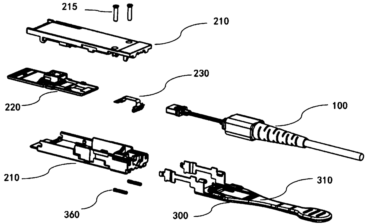
[0024] figure 1 Shown is an exploded view of the optical communication module of the present invention, Figure 6 Shown is the overall structure diagram of the optical communication module of the present invention. For details, see figure 1 , the main body of the optical communication module includes an optical cable 100, both ends of the optical cable 100 are adaptively connected...


PUM


Abstract

The invention presents an optical communication module with interconnection and fault indication functions. The optical communication module comprises an optical cable. The two ends of the optical cable are adaptively connected with photoelectric interface assemblies correspondingly. The photoelectric interface assemblies comprise shells, circuit board assemblies and signal lamp assemblies, wherein the circuit board assemblies and the signal lamp assemblies are arranged in the shells. The circuit board assemblies are in butt connection with the tail end of the optical cable for completing photovoltaic conversion and communication of optical signals in the optical cable. The signal lamp assemblies and the circuit board assemblies are welded and fixed. The signal lamp assemblies are used fordetecting the photoelectric communication condition of the circuit board assemblies. When the photoelectric communication condition is abnormal, the signal lamp assemblies can trigger an alarm lamp to be turned on, and field personnel are reminded to conduct fault diagnosis. The signal lamp assemblies are further provided with trigger switches, signal lamps at the two ends of the same optical cable are turned on and turned off simultaneously, and module interconnection indication is realized.

Description

technical field [0001] The invention belongs to the technical field of optical communication, and in particular relates to an optical communication module with functions of interconnection and fault indication. Background technique [0002] In the field of optical communication, an optical cable is usually used to connect connection modules distributed on different switches or different racks. One optical cable has two optical cable interfaces, each interface is provided with a connection module. However, since there is no obvious difference in appearance between each connecting module and optical cable, and there is no obvious pairing mark on the modules at both ends of the optical cable. Therefore, when there is a problem with the connection module at one end, it is difficult to immediately find the corresponding connection module at the other end by naked eyes. Therefore, it is time-consuming and laborious to troubleshoot the faulty module. In addition, when the commun...

Claims


Application Information

Patent Timeline
Patent Type & Authority Applications(China)
IPC IPC(8): G02B6/42
CPCG02B6/4201G02B6/4274G02B6/4281
Inventor 陈华晓施沙美孙少妹王怀亮
Owner FINISAR SHANGHAI INC
Learn More