Bridge maintenance equipment capable of working automatically

A technology for automatic work and maintenance of equipment, which is applied to parts, electrical components, coupling devices, etc. Tightness, the effect of improving work efficiency

Inactive Publication Date: 2018-06-29
XIAMEN MAIFENGWEI MACHINERY CO LTD
View PDF0 Cites 0 Cited by
  • Summary
  • Abstract
  • Description
  • Claims
  • Application Information

AI Technical Summary

Problems solved by technology

[0002] With the development of urban construction, bridge facilities have been used more and more. During the daily maintenance of bridges, electrical equipment is usually required. When using electrical equipment, the equipment is usually powered through the electrical connection frame. Traditional automatic bridge maintenance equipment is usually plugged in manually when using electricity, and automatic control operation cannot be realized. Manual plugging by personnel may result in uneven plugging force, resulting in damage to the power head. At the same time, it is easy to generate arcs when plugging Leading to electric shock accidents, there is a great potential safety hazard, and the traditional way of manual plugging also has unstable connections, and the function is single

Method used


Image

  • Bridge maintenance equipment capable of working automatically
  • Bridge maintenance equipment capable of working automatically
  • Bridge maintenance equipment capable of working automatically

Examples


Embodiment Construction

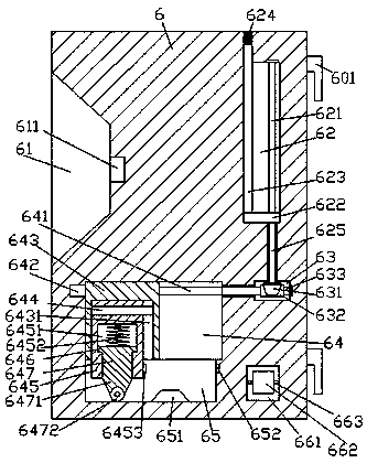
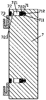
[0026] Such as Figure 1-Figure 8 As shown, an automatically working bridge maintenance equipment of the present invention includes a connecting frame body 6 and a hanging frame 7, and a control groove 61 is provided in the left end surface of the connecting frame body 6, and a control groove 61 is arranged in the control groove 61. An external electrical hole 611 is provided, and the electrical connection frame 6 is provided with a switch door 661 on the left end of the control slot 61. The left end of the switch door 661 is hinged by a hinge 663, and the external position of the switch door 661 is A handle 662 is provided at the handle 662, and the switch door 661 can be opened and closed. The hook 601 is correspondingly provided on the right end surface of the electrical connection frame 6, and the first sliding cavity is provided in the electrical connection frame 6. 64, the bottom end of the first sliding cavity 64 is provided with a guiding sliding groove 65, and the fir...


PUM


Abstract

The invention discloses bridge maintenance equipment capable of working automatically. The equipment comprises an electricity connection frame and a hanging and raising rack; an operation groove is formed in the left end surface of the electricity connection frame; an outer connection electric hole is formed in the operation groove; the electricity connection frame is provided with an opening andclosing door located at the left end surface of the operation groove; the left end surface of the opening and closing door is hinged through a hinge; the outside of the opening and closing door is provided with a handle; the right end surface of the electricity connection frame is provided with hooks which are correspond to each other in a vertical direction; a first sliding cavity is formed in the electricity connection frame; a guide sliding groove is formed in the inner bottom end of the first sliding cavity; a first spiral rod configured to extend leftwards and rightwards, is arranged in the first sliding cavity; the left end of the first spiral rod is connected with a first driving machine; the first spiral rod is connected with a first sliding block in a threaded fit manner; a firstsliding groove is formed in the first sliding block; a guide sliding rod, configured to extend leftwards and rightwards, is arranged in the first sliding groove; and the guide sliding rod is connectedwith a second sliding block in a slide fit manner. The bridge maintenance equipment of the invention has the advantages of simple structure and convenient operation. The bridge maintenance equipmentcan automatically work to supply power and realize plug-in connection. Meanwhile, the bridge maintenance equipment is convenient to install, assemble and disassemble, and is high in safety.

Description

technical field [0001] The invention relates to the technical field of bridge maintenance, in particular to an automatically working bridge maintenance equipment. Background technique [0002] With the development of urban construction, bridge facilities have been used more and more. During the daily maintenance of bridges, electrical equipment is usually required. When using electrical equipment, the equipment is usually powered through the electrical connection frame. Traditional automatic bridge maintenance equipment is usually plugged in manually when using electricity, and automatic control operation cannot be realized. Manual plugging by personnel may result in uneven plugging force, resulting in damage to the power head. At the same time, it is easy to generate arcs when plugging Cause electric shock accidents, there is a great potential safety hazard, and the traditional manual plugging method also has unstable connection, and the function is single. Contents of th...

Claims


Application Information

Patent Timeline
Patent Type & Authority Applications(China)
IPC IPC(8): H01R13/627H01R13/629H01R13/70H01R13/717
CPCH01R13/701H01R13/627H01R13/629H01R13/717
Inventor 沈菲菲
Owner XIAMEN MAIFENGWEI MACHINERY CO LTD
Why Eureka
Try Eureka